Draft Test Plan QAPP
Enclosure 1 (Generic QAPP) - rev4 clean.doc
Information Collection Effort for Facilities with Combustion Units
Draft Test Plan QAPP
OMB: 2060-0616

Summary of Test Procedures, Methods, and Reporting Requirements
This document provides an overview of approved methods, target pollutant units of measure, and reporting requirements for the boiler and process heater test plan as well as the CISWI test plan. The document is organized as follows:
1.0 Stack Testing Procedures and Methods
2.0 Fuel Analysis Procedures and Methods
3.0 Continuous Monitoring Procedures and Methods
4.0 How to Report Data
5.0 How to Submit Data
6.0 Definitions for Boiler and Process Heater Test Plan
7.0 Contact Information for Questions on Test Plan and Reporting
1.0 Stack Testing Procedures and Methods
The EPA CISWI, boiler and process heater test program includes stack test data requests for several pollutants, depending on the availability of existing test data.
If you operate a boiler or process heater, you were selected to perform a stack test for some combination of the following pollutants: Carbon monoxide (CO), dioxins/furans (D/F), total hydrocarbons (THC), formaldehyde, hydrogen chloride (HCl), hydrogen fluoride (HF), mercury (Hg), metals (antimony (Sb), arsenic (As), beryllium (Be), cadmium (Cd), chromium (Cr), cobalt (Co), lead (Pb), manganese (Mn), nickel (Ni), phosphorus (P) and selenium (Se)), oxides of nitrogen (NOx), sulfur dioxide (SO2) and particulate matter (PM10 ,PM2.5, and condensible PM).
If you operate a CISWI unit, you were selected to perform a stack test for some combination of the following pollutants: CO, Hg, D/F, HCl, HF, metals (Sb, As, Be, Cd, Cr, Co, Pb, Mn, Ni, P, and Se), NOx, PM10 ,PM2.5, and condensible PM, and SO2.
Refer to page 1 of the Section 114 letter you received for the specific combustion unit and pollutants we are requesting that you perform emission tests. You may have submitted test data for some of these pollutants already.
1.1 How to Select Sample Location and Gas Composition Analysis Methods
U.S. EPA Method 1 of Appendix A of Part 60 must be used to select the locations and number of traverse points for sampling. See http://www.epa.gov/ttn/emc/methods/method1.html for a copy of the method and guidance information.
Analysis of flue gas composition, including oxygen concentration, must be performed using U.S. EPA Methods 3A or 3B of Appendix A of Part 60. See http://www.epa.gov/ttn/emc/methods/method3a.html for Method 3A or http://www.epa.gov/ttn/emc/methods/method3b.html for Method 3B information.
1.2 Boiler and Process Heater Test Methods and Reporting
Table 1.2 presents a summary of the recommended boiler test methods for each pollutant and possible alternative methods. If you would like to use a method not on this list, and the list does not meet the definition of “equivalent” provided in the definitions section of this document, please contact EPA for approval of an alternative method.
For copies of the recommended U.S. EPA methods and additional information, please refer to EPA’s Emission Measurement Center website: http://www.epa.gov/ttn/emc/. A copy of RCRA Method 0011 for aldehydes may be obtained here: http://www.epa.gov/epawaste/hazard/testmethods/sw846/pdfs/0011.pdf.
Report pollutant emission data as specified in Table 1.2 below. All pollutant concentrations should be corrected to 7% oxygen and should be reported on the same moisture basis. Report the results of the stack tests according to the instructions in Section 4.0 of this enclosure. In addition to the emission test data, you should also report the following process information taken at the time of, and during, the emissions test: Heat input; fuel composition and feed rate; steam output; emissions control devices in use during the test; control device operating or monitoring parameters (including, as appropriate to the control device, flue gas flow rate, pressure drop, scrubber liquor pH, scrubber liquor flow rate, sorbent type and sorbent injection rate), and process parameters (such as, oxygen).
Table 1.2: Summary of Boiler and Process Heater Test Methods and Alternative Methods
Pollutant |
Recommended Method |
Alternative Method |
Target Reported Units of Measure |
CO |
U.S. EPA Method 10, 10A, or 10B |
None
|
ppmvd @ 7% O2 |
Formaldehyde |
RCRA Method 0011 |
NCASI BHA method |
ppmvd @ 7% O2 |
HCl and HF |
U.S. EPA Method 26A |
U.S. EPA Method 26 if there are no entrained water droplets in the sample. |
lb/mmBtu |
Hg |
U.S. EPA Method 29* |
ASTM-D6784-02 (Ontario Hydro Method) U.S. EPA Method 101A |
lb/mmBtu |
Metals |
U.S. EPA Method 29* |
U.S. EPA Method 12 may be used for Pb. |
lb/mmBtu |
PM (10, filterable) |
Other Test Method 27 (OTM 27) |
U.S. EPA Method 5 (filterable), U.S. EPA Method 17 |
lb/mmBtu |
PM (2.5) |
Other Test Method 27 (OTM 27) |
None |
lb/mmBtu |
PM (condensible) |
Other Test Method 28 (OTM 28) |
None |
lb/mmBtu |
THC |
U.S. EPA Method 25A |
None |
ppmvd @ 7% O2 |
D/F |
U.S. EPA Method 23 |
None |
ng/dscm @ 7% O2 |
NOx |
U.S. EPA Method 7E |
U.S. EPA Method 7, 7A, 7B, 7C, or 7D |
ppmvd @ 7% O2 |
SO2 |
U.S. EPA Method 6C |
U.S. EPA Method 6 |
ppmvd @ 7% O2 |
O2 |
U.S. EPA Method 3A |
U.S. EPA Method 3 |
% |
Moisture |
U.S. EPA Method 4 |
None |
% |
*If both mercury and other metals will be testing using EPA Method 29, the stack test company should be diligent in the set-up and handling of the impingers to avoid cross contamination of the manganese from the permanganate into the metals catch. Alternately, the contractor may want to collect mercury on a separate train from the train used to collect the other metals.
1.3 CISWI Test Methods and Reporting
Table 1.3 presents a summary of the recommended CISWI test methods for each pollutant and possible alternative methods. For copies of the recommended U.S. EPA methods and additional information, please refer to EPA’s Emission Measurement Center website: http://www.epa.gov/ttn/emc/. If you would like to use a method not on this list, please contact EPA for approval of an alternative method.
All pollutant concentrations should be corrected to 7% oxygen and should be reported on the same moisture basis. The recommended units of concentration for each pollutant vary, and are listed in Table 1.3. Report the results of your stack tests according the directions provided in Section 4.0 of this enclosure. In addition to the emission test data, we also require a report of the following process information taken at the time of the emissions test: Heat input; fuel/waste description, composition and feed rate; steam or hot water output (if the CISWI unit has a waste heat boiler); emissions control devices in use during the test; control device operating or monitoring parameters ( including, as appropriate to the control device, flue gas flow rate, pressure drop, scrubber liquor pH, scrubber liquor flow rate, sorbent type and sorbent injection rate).
Table 1.3: Summary of CISWI Test Methods and Alternative Methods
Pollutant |
Recommended Method |
Alternative Method |
Concentration Units (@ 7% O2) |
Cd |
U.S. EPA Method 29 |
None |
mg/dscm |
CO |
U.S. EPA Method 10, 10A or 10B |
None |
ppmvd |
D/F |
U.S. EPA Method 23 |
None |
ng/dscm |
HCl and HF |
U.S. EPA Method 26A |
U.S. EPA Method 26 if there are no entrained water droplets in the sample. |
ppmvd |
Hg |
U.S. EPA Method 29* |
ASTM-D6784-02 (Ontario Hydro Method) |
mg/dscm |
Metals |
U.S. EPA Method 29* |
U.S. EPA Method 12 may be used for Pb. |
mg/dscm |
PM10 (filterable) |
Other Test Method 27 (OTM 27) |
U.S. EPA Method 5 |
mg/dscm |
PM2.5 |
Other Test Method 27 (OTM 27) |
None |
mg/dscm |
PM (condensible) |
Other Test Method 28 (OTM 28) |
None |
mg/dscm |
NOx |
U.S. EPA Method 7E |
U.S. EPA Method 7, 7A, 7B, 7C, or 7D |
ppmvd |
SO2 |
U.S. EPA Method 6C |
U.S. EPA Method 6 |
ppmvd |
O2 |
U.S. EPA Method 3A |
U.S. EPA Method 3 |
% |
Moisture |
U.S. EPA Method 4 |
None |
% |
*If both mercury and other metals will be testing using EPA Method 29, the stack test company should be diligent in the set-up and handling of the impingers to avoid cross contamination of the manganese from the permanganate into the metals catch. Alternately, the contractor may want to collect mercury on a separate train from the train used to collect the other metals.
2.0 Fuel Analysis Procedures and Methods
The EPA boiler and process heater test program is requesting fuel variability data for fuel-based HAPs. The fuel analyses requested include: mercury, chlorine, fluorine, and metals (antimony, arsenic, beryllium, cadmium, chromium, cobalt, lead, manganese, nickel, phosphorus, and selenium) for any boiler or process heater firing solid or liquid fuels that is selected to conduct a stack test.
You will need to conduct one fuel sample (comprised of three composite samples, each individually analyzed) of the fuel used during the stack test and nine additional fuel analyses (each comprised of three composite samples) spread across even intervals of a 30-day testing period.
Refer to page 1 of the Section 114 letter you received for the specific types of fuel analyses we are requesting from your facility. Directions for collecting, compositing, preparing, and analyzing fuel analysis data are outlined in Sections 2.1 through 2.4.
2.1 How to Collect a Fuel Sample
Table 2.1 outlines a summary of how samples should be collected. Alternately, you may use the procedures in ASTM D2234–00 (for coal) or ASTM D6323–98 (2003) (for biomass) to collect the sample.
Table 2.1: Summary of Sample Collection Procedures
Sampling Location |
Sampling Procedures |
Sample Collection Timing |
Solid Fuels |
||
Belt or Screw Feeder |
Stop the belt and withdraw a 6- inch wide sample from the full cross-section of the stopped belt to obtain a minimum two pounds of sample. Collect all the material (fines and coarse) in the full cross-section.
Transfer the sample to a clean plastic bag for further processing as specified in Sections 2.2 through 2.5 of this document.
|
Each composite sample will consist of a minimum of three samples collected at approximately equal intervals during the testing period.
|
Fuel Pile or Truck |
For each composite sample, select a minimum of five sampling locations uniformly spaced over the surface of the pile.
At each sampling site, dig into the pile to a depth of 18 inches. Insert a clean flat square shovel into the hole and withdraw a sample, making sure that large pieces do not fall off during sampling.
Transfer all samples to a clean plastic bag for further processing as specified in Sections 2.2 through 2.5 of this document. |
|
Liquid Fuels |
||
Manual Sampling |
Follow collection methods outlined in ASTM D 4057 |
|
Automatic Sampling |
Follow collection methods outlined in ASTM D4177 |
|
Fuel Supplier Analysis |
||
Fuel Supplier |
If you will be using fuel analysis from a fuel supplier in lieu of site specific sampling and analysis, the fuel supplier must collect the sample as specified above and prepare the sample according to methods specified in Sections 2.2 through 2.5 of this document. |
|
2.2 Create a Composite Sample for Solid Fuels
Follow the seven steps listed below to composite each sample:
(1) Thoroughly mix and pour the entire composite sample over a clean plastic sheet.
(2) Break sample pieces larger than 3 inches into smaller sizes.
(3) Make a pie shape with the entire composite sample and subdivide it into four equal parts.
(4) Separate one of the quarter samples as the first subset.
(5) If this subset is too large for grinding, repeat step 3 with the quarter sample and obtain a one-quarter subset from this sample.
(6) Grind the sample in a mill according to ASTM E829-94, or for selenium sampling according to SW-846-7740.
(7) Use the procedure in step 3 of this section to obtain a one quarter subsample for analysis. If the quarter sample is too large, subdivide it further using step 3.
2.3 Prepare Sample for Analysis
Use the methods listed in Table 2.2 to prepare your composite samples for analysis.
Table 2.2 Methods for Preparing Composite Samples
Fuel Type |
Method |
Solid |
SW-846-3050B or EPA 3050 for total selected metal preparation |
Liquid |
SW-846-3020A or any SW-846 sample digestion procedures giving measures of total metal |
Coal |
ASTM D2013-04 |
Biomass |
ASTM D5198-92 (2003) or equivalent, EPA 3050, or TAPPI T266 for total selected metal preparation |
2.4 Analyzing Fuel Sample
Table 2.3 outlines a list of approved methods for analyzing fuel samplings. If you would like to use a method not on this list, and the list does not meet the definition of “equivalent” provided in Section 6 of this document, please contact EPA for approval of an alternative method.
Table 2.3 List of Analytical Methods for Fuel Analysis
Analyte |
Fuel Type |
Method |
Target Reported Units of Measure |
Higher Heating Value |
Coal |
ASTM D5865–04, ASTM D240, ASTM E711-87 (1996) |
Btu/lb |
Biomass |
ASTM E711–87 (1996) or equivalent, ASTM D240, or ASTM D5865-04 |
||
Other Solids |
ASTM-5865-03a, ASTM D240, ASTM E711-87 (1997) |
||
Liquid |
ASTM-5865-03a, ASTM D240, ASTM E711-87 (1996) |
||
Moisture |
Coal, Biomass, Other Solids |
ASTM-D3 173-03, ASTM E871-82 (1998) or equivalent, EPA 160.3 Mod., or ASTM D2691-95 for coal. |
% |
Mercury Concentration |
Coal |
ASTM D6722-01, EPA Method 1631E, SW-846-1631, EPA 821-R-01-013, or equivalent |
ppm |
Biomass |
SW-846-7471A, EPA Method 1631E, SW-846-1631, ASTM D6722-01, EPA 821-R-01-013, or equivalent |
||
Other Solids |
SW-846-7471A, EPA Method 1631E, SW-846-1631, EPA 821-R-01-013, or equivalent |
||
Liquid |
SW-846-7470A, EPA Method 1631E, SW-846-1631E, SW-846-1631, EPA 821-R-01-013, or equivalent |
||
Total Selected Metals Concentration |
Coal |
SW-846-6010B, ASTM D3683-94 (2000), SW-846-6020, -6020A or ASTM D6357-04 (for arsenic, beryllium, cadmium, chromium, lead, manganese, and nickel in coal) ASTM D4606-03 or SW-846-7740 (for Se) SW-846-7060 or 7060A (for As) |
ppm |
Biomass |
SW-846-6010B, ASTM D6357-04, SW-846-6020, -6020A, EPA 200.8, or ASTM E885-88 (1996) or equivalent, SW-846-7740 (for Se) SW-846-7060 or -7060A (for As) |
||
Other Solids |
SW-846-6010B, EPA 200.8 SW-846-7060 or 7060A for As |
||
Liquid |
SW-846-6020, -6020A, , SW-846-6010B, SW-846-7740 for Se, SW-846-7060 or -7060A for As |
||
Chlorine Concentration |
Coal |
SW-846-9250 or ASTM D6721-01 or equivalent, SW-846-5050, -9056, -9076, or -9250, ASTM E776-87 (1996) |
ppm |
Biomass, Other Solids, Liquids |
ASTM E776-87 (1996), SW-846-9250, SW-846-5050, -9056, -9076, or -9250 |
||
Fluorine Concentration |
Coal |
ASTM D3761-96(2002), D5987-96(2002) |
ppm |
Report the results of your fuel analysis according to the directions provided in section 4.0 of this enclosure.
3.0 Continuous Monitoring Procedures and Methods
If your combustion unit was selected to conduct a CO and THC variability analysis, the unit was identified as being a best performing unit for CO emissions within the unit’s preliminary subcategory. You will need to complete a 30-day variability monitoring for CO emissions (using CO CEMS) and THC emissions (using a THC Analyzer). O2 levels at the location of the monitors will also be continuously monitored and reported.
3.1 General Requirements for Temporary or Installed Monitoring Equipment and QA/QC Procedures for Monitoring Data
If CO CEMS or hydrocarbon monitors are installed at the site and meet the criteria mentioned in 3.1.1 and 3.1.2 below, the installed equipment should be used to collect the monitoring data. If no CO CEMS or THC analyzers are installed, or if the CEMS or analyzers do not meet the criteria listed in 3.1.1 and 3.1.2 below, temporary equipment should be used to collect the data.
3.1.1 CO CEMS
CO CEMS used to obtain the CO monitoring data for this study must meet the requirements specified in Performance Specification 4. CO CEMS monitoring should follow quality assurance and quality control procedures as specified in Performance Specification 4.
(see: http://www.epa.gov/ttn/emc/perfspec/ps-4.html).
3.1.2 Hydrocarbon Monitor/THC Analyzer
The monitor used for comparative CO/THC monitoring must have the ability to automatically cycle between THC and methane (CH4) only collection modes. Additionally, the equipment should comply with requirements specified in EPA Method 25A. THC CEMS used to obtain the THC monitoring data for this study must meet the requirements specified in Performance Specification 8A. THC monitoring should follow quality assurance and quality control procedures as specified in Performance Specification 8A
(see: http://www.epa.gov/ttn/emc/specs/prompspec8a.html).
3.3 Monitoring Procedures
3.3.2 CO Variability Monitoring Procedures
The purpose of the CO variability monitoring is to assess how changes in normal unit operations will effect CO emissions. For each unit selected for CO variability monitoring, the facility will monitor CO emissions, oxygen levels, heat input, and steam output continuously for a 30-day period. While the monitoring devices are installed, the unit will operate as normally scheduled to account for normal fluctuations in load and fuel mix.
Report the results of your 30-day monitoring according to the directions provided in Section 4.0 of this enclosure.
4.0 How to Report Data
The method for reporting the results of any testing and monitoring requests depend on the type of tests and the type of methods used to complete the test requirements. This section discusses the requirements for reporting the data.
4.1 Reporting stack test data
If you conducted a stack test using one of the methods listed in Table 4.1, (Method 6C, Method 7E, Method 10, Method 17, Method 25A, Method 26A, Method 29, Method 101, Method 101A, Method 201A, Method 202) you must report your data using the EPA Electronic Reporting Tool (ERT) Version 3. At present, only these methods are supported by the ERT. ERT is a Microsoft ® Access database application. Two versions of the ERT application are available. If you are not a registered owner of Microsoft ® Access, you can install the runtime version of the ERT Application. Both versions of the ERT are available at http://www.epa.gov/ttn/chief/ert/ert_tool.html . The ERT supports an Excel spreadsheet application (which is included in the files downloaded with the ERT) to document the collection of the field sampling data. After completing the ERT, will also need to attach an electronic copy of the emission test report (PDF format preferred) to the Attachments module of the ERT.
Table 4.1 List of Test Methods Supported by ERT
Test Methods Supported by ERT |
Methods 1 through 4 |
Method 7E |
Method 6C |
Method 5 |
Method 3A |
Method 29 |
Method 26A |
Method 25A |
Method 202 |
Method 201A |
Method 17 |
Method 101A |
Method 101 |
Method 10 |
CT Method 40 |
CT Method 39 |
If you conducted a stack test using a method not currently supported by the ERT, you must report the results of this test in a Microsoft ® Excel Emission Test Template. The Excel templates are specific to each pollutant and type of unit and they can be downloaded from (insert link). You must report the results of each test on appropriately labeled worksheet corresponding to the specific tests requested at your combustion unit. If more than one unit at your facility conducted a stack test using methods not currently supported by the ERT, you must make a copy of the worksheet and update the combustor ID in order to distinguish between each separate test. After completing the worksheet, you must also submit an electronic copy of the emission test report (PDF format preferred).
4.2 Reporting Fuel Analysis Data
If you conducted a fuel analysis, you must report the analysis results separately for each of the 12 samples in a Microsoft ® Excel Fuel Analysis Template. The fuel samples collected in conjunction with the stack test are comprised of three composite samples, each of which is analyzed separately. The remaining nine additional fuel samples are also comprised of three composite samples, but only the combined composite samples are analyzed. The Excel template can be downloaded from (insert link). If you conducted fuel analysis on more than one type of fuel used during testing, or for more than one combustion unit, you must make a copy of the worksheet and update the combustor ID and fuel type in each worksheet order to distinguish between the separate fuel analyses.
4.3 Reporting CO/HC Monitoring Data
If you conducted CO/HC monitoring, you must report the hourly results of the 30-day monitoring in a Microsoft ® Excel CO and HC Monitoring Template. The Excel template can be downloaded from (insert link). If you conducted the monitoring on more than one combustion unit, or conducted monitoring for more than the 30-day period, you must make a copy of the worksheet and update the combustor ID in each worksheet order to distinguish between separate combustion units or separate monitoring periods. In addition to completing the Excel template, you must also submit the following QC items:
Results of Relative Accuracy Test Audits (RATA)
Charted Results of Drift Tests
Protocol Gas Certificates
Summary of data and times the monitoring was conducted from field testing sheets.
4.2 Required Fields for ERT Reporting
Some of the fields contained in the ERT were already collected during the 2008 combustion survey and these data will not be recollected in the ERT. This section outlines the required data entry fields for the ERT in order to satisfy the requirements of this ICR combustion test program. Appendix A lists each field within the ERT and notes whether or not the field is required or optional.
5.0 How to Submit Data
You may submit your data in one of three ways as listed below. However, in order to avoid duplicate data and keep all data for a particular facility together, we request that you submit all of the data requested from your facility in the same way. To submit your data:
E-mail an electronic copy of all requested files to [email protected]
If the files are too large for your e-mail system, you may upload the electronic files to a FTP site (see directions for FTP site procedures below)
Mail a CD or DVD containing an electronic copy of all requested files to the EPA address shown in your Section 114 letter. If no electronic copy is available, mail a hard copy of all requested files to the EPA address shown in your Section 114 letter.
The steps below outline how to upload files to the FTP site by using “My Computer” as well as by using an FTP Client software.
Directions for accessing the FTP site via “My Computer”…
Step 1: Go to “My Computer” and enter ftp://combustionsurvey:[email protected] in the address bar. A window will open containing other files that have been uploaded to the FTP.
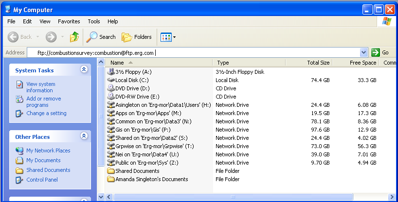
Step 2: Create a folder containing all of your survey response files. You may name the folder as follows, without using any spaces in the folder name: “StateAbbreviation_FacilityName_City” (e.g., NC_ NCStateUniversity_Raleigh). Copy and paste the entire folder from your computer to the window pointing to ftp://combustionsurvey:[email protected].
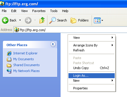
Step 3: If you get an error saying you do not have permission to put files on the server, you may need to manually enter a username and password. Otherwise proceed to step 4.

Step 3a: To manually enter a username and password, Right click on your mouse inside the FTP window and select "login as".
Step 3b: Enter Username: "combustionsurvey" and password "combustion".
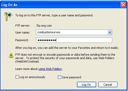
Step 3c: Copy and paste your files from your computer to the FTP site.
Step 4: To ensure that your files have been uploaded, please wait for the file transfer to complete before shutting the FTP window.
Step 5: Send an e-mail to [email protected] that lists the names of the folders you have uploaded to the FTP site.
Directions for accessing the FTP site via an FTP Client Software…
FTP Client software programs prevent FTP timeout errors and are available for free on the internet. Contact your MIS support staff for instructions on your company FTP software or download a copy of FileZilla Client FTP software at (http://filezilla-project.org/download.php).
Step 1: Download and Install FTP Client Software.
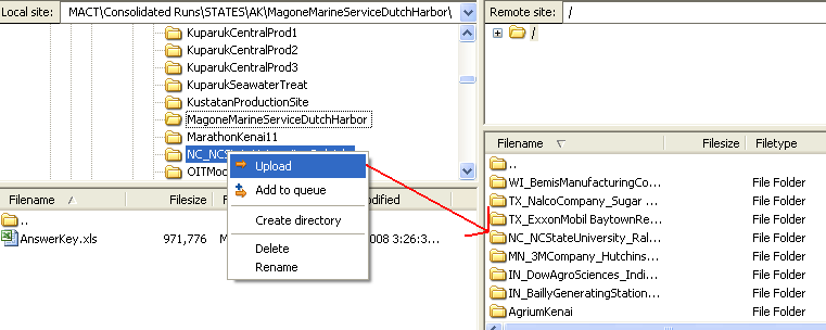
Step 2: Enter host “ftp.erg.com”, Username: “combustionsurvey”, and Password: “combustion”. Then select the “Quickconnect” button. A screenshot of how this looks in Filezilla is shown below.

Step 3: Go to the “Local site” window in FileZilla (or other FTP Client software) and navigate to the location where your files are saved. Be sure to name the folder containing your files as follows: “StateAbbreviation_FacilityName_City” (e.g., NC_ NCStateUniversity_Raleigh).
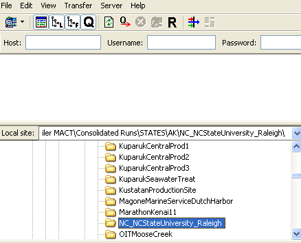
Step 4: Right click on the folder containing your files to be submitted and select “upload”. The file should automatically copy to the remote site location on FTP site. In the figure below the folder “NC-NCStateUniversity_Raleigh” was uploaded to the FTP site and now appears in the remote site window. You can click on the folder in the remote site window to ensure that all the folder contents have uploaded correctly.
Step 5: Send an e-mail to [email protected] that lists the names of the folders you have uploaded to the FTP site.
6.0 Definitions for Boiler and Process Heater Test Plan
The following definitions apply to the boiler and process heater test plan methods:
Equivalent means:
(1) An equivalent sample collection procedure means a published voluntary consensus standard or practice (VCS) or EPA method that includes collection of a minimum of three composite fuel samples, with each composite consisting of a minimum of three increments collected at approximately equal intervals over the test period.
(2) An equivalent sample compositing procedure means a published VCS or EPA method to systematically mix and obtain a representative subsample (part) of the composite sample.
(3) An equivalent sample preparation procedure means a published VCS or EPA method that: Clearly states that the standard, practice or method is appropriate for the pollutant and the fuel matrix; or is cited as an appropriate sample preparation standard, practice or method for the pollutant in the chosen VCS or EPA determinative or analytical method.
(4) An equivalent procedure for determining heat content means a published VCS or EPA method to obtain gross calorific (or higher heating) value.
(5) An equivalent procedure for determining fuel moisture content means a published VCS or EPA method to obtain moisture content. If the sample analysis plan calls for determining metals (especially the mercury, selenium, or arsenic) using an aliquot of the dried sample, then the drying temperature must be modified to prevent vaporizing these metals. On the other hand, if metals analysis is done on an ‘‘as received’’ basis, a separate aliquot can be dried to determine moisture content and the metals concentration mathematically adjusted to a dry basis.
(6) An equivalent pollutant (mercury, TSM, or total chlorine) determinative or analytical procedure means a published VCS or EPA method that clearly states that the standard, practice, or method is appropriate for the pollutant and the fuel matrix and has a published detection limit equal or lower than the methods listed in this test plan.
Voluntary Consensus Standards or VCS mean technical standards (e.g.,materials specifications, test methods, sampling procedures, business practices) developed or adopted by one or more voluntary consensus bodies. EPA/OAQPS has by precedent only used VCS that are written in English. Examples of VCS bodies are: American Society of Testing and Materials (ASTM), American Society of Mechanical Engineers (ASME), International Standards Organization (ISO), Standards Australia (AS), British Standards (BS), Canadian Standards (CSA), European Standard (EN or CEN) and German Engineering Standards (VDI). The types of standards that are not considered VCS are standards developed by: the U.S. states, e.g., California (CARB) and Texas (TCEQ); industry groups, such as American Petroleum Institute (API), Gas Processors Association (GPA), and Gas Research Institute (GRI); and other branches of the U.S. government, e.g. Department of Defense (DOD) and Department of Transportation (DOT).
This does not preclude EPA from using standards developed by groups that are not VCS bodies within their rule. When this occurs, EPA has done searches and reviews for VCS equivalent to these non-EPA methods.
7.0 Contact Information for Questions on Test Plan and Reporting
For questions on how to report data using the ERT, contact:
Ron Meyers
U.S. EPA
919.541.5407
For questions on the boiler and process heater test plan, including units selected to test, test methods, reporting mechanisms other than the ERT, contact:
Jim Eddinger
U.S. EPA
919.541.5426
For questions on the CISWI test plan, including units selected to test, test methods, reporting mechanisms other than the ERT, contact:
Brian Shrager
U.S. EPA
919.541.7689
For questions on uploading files to the FTP site, contact:
Graham Gibson
ERG (contractor support)
919.468.7823
QAPP – Section 114 Enclosure 1
| File Type | application/msword |
| Author | ASingleton |
| Last Modified By | ASingleton |
| File Modified | 2009-05-08 |
| File Created | 2009-05-08 |
© 2025 OMB.report | Privacy Policy