The Boundary and Annexation Survey (BAS)
The Boundary and Annexation Survey (BAS)
06_Attachment D5_DigitalBAS_Tribal
The Boundary and Annexation Survey (BAS)
OMB: 0607-0151
Boundary and Annexation Survey Respondent Guide: Tribal Digital BAS |
Issued June 2007 |
|
||
|
|
|||
|
|
|
||
|
|
|
||
SECTION NUMBER |
SECTION TITLE |
PAGE |
||
1 |
Introduction to the Tribal Digital Boundary and Annexation Survey (BAS) |
3 |
||
1.1 |
Overview of the Tribal BAS |
3 |
||
1.2 |
Key Dates for Tribal Digital BAS Participants |
3 |
||
2 |
MAF/TIGER Accuracy Improvement Project (MTAIP) |
4 |
||
3 |
Topological Relationships and Spatial Accuracy |
5 |
||
3.1 |
Topological Relationships in the MAF/TIGER Database |
5 |
||
3.2 |
GIS and Spatial Accuracy |
6 |
||
4 |
Census Bureau Provided Shapefiles |
8 |
||
5 |
Census Bureau Geocoding |
9 |
||
6 |
Updating the Census Bureau Shapefiles |
9 |
||
6.1 |
General File Setup Guidelines |
9 |
||
6.2 |
Changing Our Coordinate System to Match Yours |
9 |
||
6.3 |
Additions, Deletions, and Boundary Corrections |
10 |
||
6.4 |
Tribal Subdivisions |
11 |
||
6.4.1 |
Criteria for Defining Tribal Subdivisions |
11 |
||
6.4.2 |
Updating Tribal Subdivisions |
12 |
||
6.5 |
Linear Feature Updates |
12 |
||
6.5.1 |
Address Range Break Updates |
14 |
||
6.6 |
Area Landmarks, Hydro Areas, and Point Landmarks |
14 |
||
6.6.1 |
Area Landmark and Hydro Area Updates |
14 |
||
6.6.2 |
Point Landmark Updates |
16 |
||
6.7 |
Reviewing Changes to the Census Bureau Shapefiles |
16 |
||
6.7.1 |
Geographic Offsets and Corridors |
18 |
||
6.7.2 |
Boundary Corrections |
20 |
||
6.7.3 |
Linear Feature Updates |
21 |
||
6.7.4 |
Additional Review Information |
22 |
||
6.8 |
Submitting Metadata with the Digital File |
22 |
||
6.9 |
Submitting Digital Data |
23 |
||
6.9.1 |
AIA, ANRC, Tribal Subdivision, and Hawaiian Homeland Submissions (Change Polygons) |
24 |
||
6.9.2 |
AIA, ANRC, Tribal Subdivision, and Hawaiian Homeland Submissions (Whole Entity Polygons) |
24 |
||
6.9.3 |
Linear Feature, Area Landmark / Hydro Areas & Point Landmark Updates |
25 |
||
6.9.4 |
Compressing the Digital Files |
25 |
||
6.9.5 |
Submitting Digital Files via File Transfer Protocol (FTP) |
25 |
||
6.9.6 |
Additional Information |
26 |
||
Appendix 1 |
Paperwork Reduction Project |
27 |
||
Appendix 2 |
Census Bureau Regional Offices – Contact Information |
28 |
||
Appendix 3 |
Required Fields and Coding Scheme |
29 |
||
Appendix 4 |
Data Dictionary |
31 |
||
A
|
Example Processes 1 & 2 |
36 |
||
1. Introduction to the Tribal Digital Boundary and Annexation Survey (BAS)
Overview of the Tribal BAS
The Census Bureau conducts the Tribal Boundary and Annexation Survey (BAS) annually to collect boundary information about federally recognized American Indian reservations, including off-reservation trust lands and tribal subdivisions. The Census Bureau’s primary purpose for delineating tribal boundaries is to develop the best possible geographic framework for the tabulation and presentation of statistical information. For tribal governments with reservations or off-reservation trust lands, the Census Bureau developed the tribal BAS to obtain and maintain the most current, legally established boundaries of reservations and off-reservation trust lands.
In support of the government-to-government relationship with federally recognized American Indian tribes, the Census Bureau works directly with tribal officials to maintain a current and comprehensive inventory of correct names, legal descriptions and legal boundaries for federally recognized tribes with reservations and/or off-reservation trust lands. Through the BAS, the Census Bureau updates reservation, off-reservation trust land and tribal subdivision boundaries, as well as their names and features (features such as roads or rivers), and address information at the boundaries. The information collected is used to tabulate data from various programs and surveys, such as the American Community Survey and 2010 Census. Maintaining these boundaries and boundary-to-feature relationships correctly through the BAS makes certain that the appropriate population is assigned to your area.
If there are changes to the boundary of your AIA, the Census Bureau appreciates your cooperation in completing the BAS forms (offered in either paper or electronic form), marking changes on the maps, and returning the maps and forms to the Census Bureau by April 1st.
Legal Disputes: If a tribal government disagrees with the Census Bureau’s depiction of their boundary and provides supporting documents that pre-date 1990 when our boundaries were last sanctioned by the BIA, we ask for clarification from the U.S. Department of the Interior, Office of the Solicitor regarding the correct current boundary. Often complicated legal land issues require an extended period of time for resolution, and in those cases, the Census Bureau retains the boundary we have in our database until a legal opinion is issued by the Solicitor’s office.
In compliance with the Office of Management and Budget Circular A-16, the BAS supports the Census Bureau’s spatial data steward responsibilities for the Federal Geographic Data Committee and the Geospatial One-Stop by updating the inventory of, and boundaries for, governmental units. In addition, the BAS is the source of up-to-date information on boundaries, codes, and names for the U.S. Geological Survey’s (USGS) National Map and the Geographic Names Information System.
Key Dates for Tribal Digital BAS Participants
All changes received by April 1st, will be reflected in the Population Estimates Program and the American Community Survey. If the Census Bureau receives your updates by May 31st, they will be included in your Tribal BAS materials next year.
To change your method of participation in BAS from Tribal Digital BAS to MTPS or paper, you must notify the Census Bureau by February 15th. You can contact the Census Bureau by phone at (800) 972-5651 or by email at [email protected].
Additionally, to participate in the Tribal Digital BAS your entity must meet the following requirements:
The county(s) in which your tribal area is located all must have completed the realignment process for the MAF/TIGER Accuracy Improvement Project (MTAIP). The current list of counties that have completed the realignment process is posted on our Web site at: http://www.census.gov/geo/www/bas/bashome.html.
You must have the ability to edit a Census Bureau shapefile1 extract of your tribal area. We require that you update the Census Bureau shapefile with boundary and any boundary related feature changes, rather than submit a shapefile from your own local Geographic Information System (GIS).
You must provide information for the tribal BAS point of contact, the person updating the shapefiles, and the tribal chair.
You must provide legal documentation, such as trust deeds and court orders, and effective dates for all boundary changes (additions and deletions).
If you have any questions or concerns about the participation requirements, please contact the Legal Areas Team at 301-763-1099 or email [email protected].
2. MAF/TIGER Accuracy Improvement Project (MTAIP)
The principle
requirement for participating in the Tribal Digital BAS program is
that the county(s) where your tribe exists must have completed the
MTAIP process. The Census Bureau has embarked on an initiative to
enhance and streamline the MAF/TIGER system. This effort is referred
to as MTAIP. The Census Bureau’s goal for MTAIP is to
spatially improve features and boundaries in the TIGER database. The
Census Bureau is currently in the process of updating TIGER based on
digital files submitted by state, local, and tribal governments.
This is because many state, local, and tribal governments have
geographic information systems (GIS) that maintain a significantly
greater level of positional accuracy than that in the TIGER database,
and also meet our minimum accuracy requirements. Once acquired, the
Census Bureau evaluates the various layers associated with the
file(s) submitted and determines whether the file(s) can be used for
the MTAIP process. Because we are improving feature and boundary
coordinates based on state, local, and tribal MTAIP submissions,
there is a greater likelihood that Digital
Tribal BAS
submissions from the aforementioned governments will closely align
with modified TIGER making both boundary corrections and legal
changes easier to identify. This will also create a solid common
geographic foundation for future boundary exchange for governments
that have participated in the MTAIP process. If you have additional
questions about the MTAIP process, please contact a geographer at
your Census Bureau Regional Office. The contact information is
located in Appendix 2, on page 26.
3. Topological Relationships and Spatial Accuracy
The Geography Division of the Census Bureau is responsible for developing geographic applications and executing the geographic and cartographic activities needed to support the Census Bureau in collecting and disseminating census data. For the past twenty years, the Census Bureau’s TIGER and Master Address File (MAF) have become the two most critical geographic resources for supporting the Census Bureau in its collection and dissemination of data.
The following section will describe how the Census Bureau uses a topologically integrated system and how this differs from a traditional GIS system using separate layers of data.
Topological Relationships in the MAF/TIGER Database
For its use in MAF/TIGER, topology can be described as the relationship between different levels of geography. MAF/TIGER is a topologically integrated geographic database in which the topological structures define the location, connection, and relative relationship of streets, rivers, railroads, and other features to each other, and to the numerous geographic entities for which the Census Bureau tabulates data for its censuses and sample surveys. Instead of having a layer for each feature class (i.e. roads, American Indian areas, block boundary, and school district boundary) all information is stored in one layer or file. Examples 3.1.1 and 3.1.2 provide a visual interpretation of how a file is topologically integrated in MAF/TIGER.
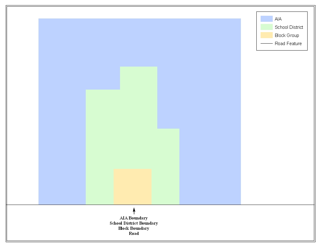
Example 3.1.1: This example shows how a road in TIGER can also represent an American Indian area, a block boundary, and a school district boundary.
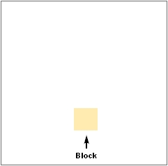
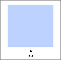
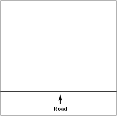
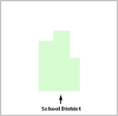


Example 3.1.2: This example shows how four different feature classes are topologically integrated into one layer. The file is topologically integrated so that the one road represents not only a road, but also an American Indian area, a block boundary, and a school district boundary.
GIS and Spatial Accuracy
In a GIS, feature classes are not often topologically integrated. Instead feature classes stand alone in separate layers that contain a high level of spatial or coordinate accuracy. When overlaying these layers in a GIS one may find that the layers may not be coincident with one another as they are in the MAF/TIGER database. Examples 3.2.1 and 3.2.2 show how files that are not integrated may appear in a GIS when they are overlaid on top of one another.
The spatial differences found between the local GIS file and the Census Bureau’s integrated file are often very small (i.e. often less than five or ten feet) and can create boundary-to-feature relationship issues for the Census Bureau. Section 6.7 provides instructions on how to review your digital submission for small spatial boundary corrections, as well as some of the potential consequences of making spatial boundary corrections that dissolve the topological relationships present in the MAF/TIGER database. Example processes detailing suggested methods on how to make your boundary changes correctly can be found in Appendix 5.
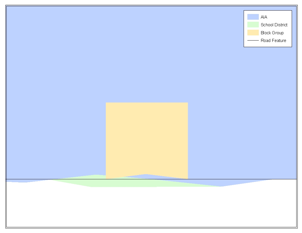
Example 3.2.1: This example shows how four different feature classes with a high level of spatial accuracy can be overlaid and shown not to be topologically integrated. The American Indian area, block, and school district boundaries, which are supposed to be coincident with the road feature, are now offset in several instances.
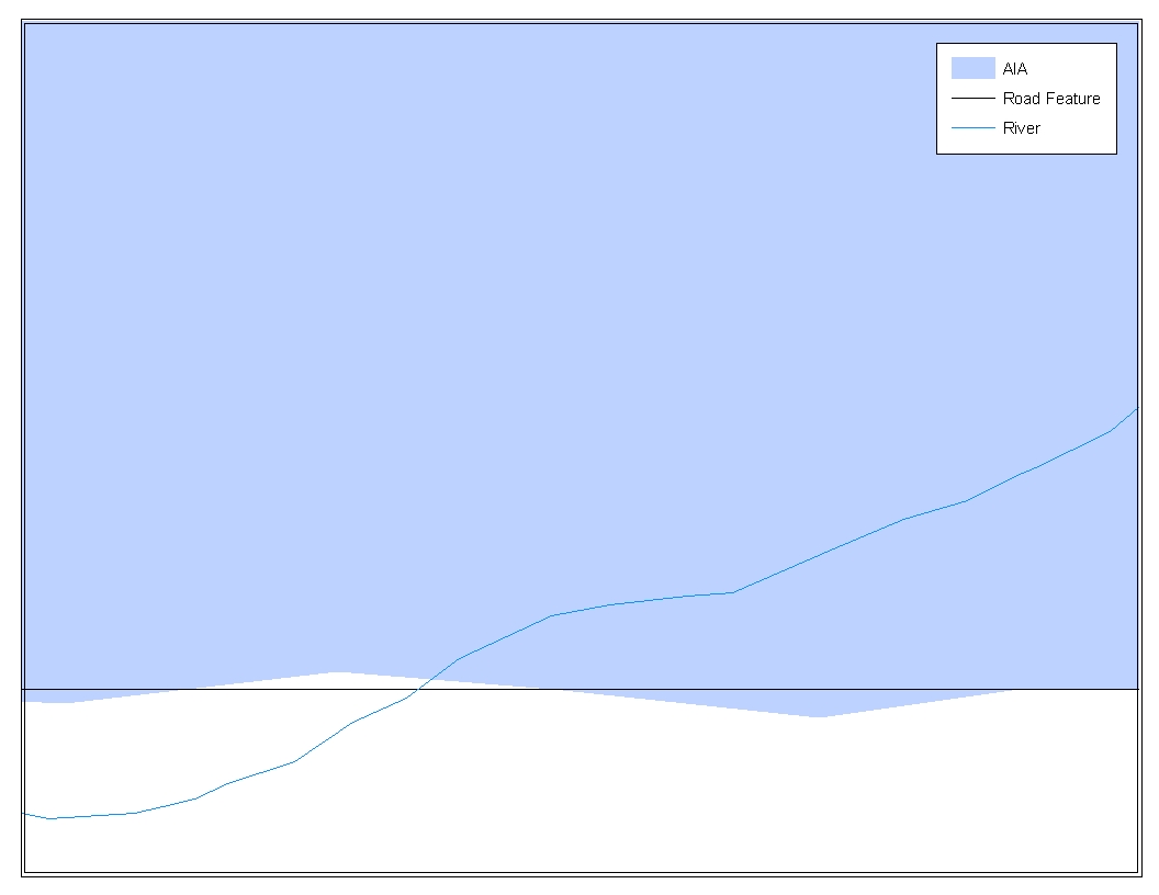


Example 3.2.2: This example depicts a situation where an American Indian area boundary is not coincident (topologically related) with a road feature. Assuming that the Census Bureau boundary is coincident with the road feature, making the changes represented by the arrows would dissolve the topological relationship in TIGER. Later sections will describe how to review these spatial boundary corrections, as well as discuss some of the consequences of dissolving the relationships in TIGER.
4. Census Bureau Provided Shapefiles
The Census Bureau is providing all Tribal Digital BAS participants with entity layers in Environmental Systems Research Institute (ESRI) shapefile format. The number of polygon-based shapefiles that the Census Bureau sends to each Tribal Digital BAS participant depends on the type of entities contained within each county. However, each participant, regardless of the number of geographic entities, receives only one shapefile for the linear feature network for the county.
All shapefiles provided by the Census Bureau are in the following unprojected geographic based coordinate system:
GCS_NAD83
Angular Unit: Degree (0.017453292519943299)
Prime Meridian: Greenwich (0.000000000000000000)
Datum: D_North_American_1983
Spheroid: GRS_1980
Semi-major Axis: 6378137.000000000000000
Semi-minor Axis: 6356752.314140356100000000
Inverse Flattening: 298.257222101000020000
5. Census Bureau Geocoding
Knowledge of two Census Bureau’s geocoding methods is critical for your Tribal Digital BAS submission. These two methods include using a MAF structure point to geocode an address, and geocoding addresses based on the street centerline (feature matching).
When a MAF structure point is available, the Census will geocode to the location of the structure point which was originally captured using GPS during an earlier Census Bureau operation. However, if there is no structure point available, the Census Bureau will geocode to the street centerline.
Based on the methods in which the Census Bureau geocodes, it is very important to review your Tribal Digital BAS submission to ensure that your changes are topologically related to features where appropriate, and to create and code geographic offsets and corridors wherever necessary.
6. Updating the Census Bureau Shapefiles
The following section will describe how to update the Census Bureau shapefiles to reflect any additions, deletions, boundary corrections, or linear feature changes that have occurred in your tribal area or tribal subdivisions since the last Tribal BAS survey. There will also be a brief discussion on the procedures that should be followed to submit boundary changes and documentation. Two in depth examples can also be found in Appendix 5 to supplement the brief discussion on the procedures to submit changes and documentation. Furthermore, there will be a short section on steps that should be taken to review your digital file before submitting it to the Census Bureau.
If the Census Bureau should have any problems processing the boundary or feature file that you submitted, a member of the Legal Areas Team will contact you with a feedback document to clarify the issue. If we cannot clarify the problem prior to our project deadline, your updates may not be incorporated into MAF/TIGER. We will continue to work with you to try and resolved these issues before the next Tribal BAS cycle.
General File Setup Guidelines
When you receive your shapefile, please follow the setup guidelines before beginning actual updates:
Open the CD and enclosed ZIP file to ensure that it contains the correct shapefiles for the entity that you will be making changes for.
Copy and decompress the shapefiles into a directory on your server/hard drive.
Open the shapefiles in a GIS.
Changing Our Coordinate System to Match Yours
Our files are in GCS NAD83 format. Please feel free to project these files into your local coordinate system/projection. Most GIS software packages contain projection wizards, or something similar, that allows the user to transform file coordinate systems and projections. For example, if your office uses ArcView to update files, please activate and utilize ArcView’s ‘Projection Utility Wizard’ extension. If using ArcGIS, please use its ‘Projection Utilities’ in ArcToolbox. MAF/TIGER shapefile extracts contain defined projection information in the *.PRJ file. Both ArcView and ArcGIS access the *.PRJ file for projection information; therefore, there is no need for you to define these parameters before changing the file coordinate systems.
After completing your updates, you may submit the boundary shapefile using your local coordinate system/projection provided that the shapefile's coordinate system contains a defined projection file (i.e., *.PRJ file) and spatial reference materials (i.e., metadata).
Additions, Deletions, and Boundary Corrections
In order to update MAF/TIGER, a separate change polygon layer must be created for each updated entity type (i.e. AIA’s, ANRC’s, Tribal Subdivisions, or Hawaiian Homelands). The change polygons must be created in relation to the current MAF/TIGER boundary.
Attribute information is also required for each change polygon. Using an AIA as an example, Table 6.3.1 provides an explanation of the fields that must be populated in the attribute table for each change polygon type.
-Required Attributes (Change Polygons)- |
|||||||
|
NAME |
CHNG_TYPE |
EFF_DATE |
DOCU |
OFFSET |
AREA |
RELATE |
Addition |
X |
X |
X |
X |
|
|
|
Deletion |
X |
X |
X |
X |
|
|
|
Boundary Correction |
X |
X |
|
|
|
|
X (IN / OUT) |
Geographic Offset |
|
X |
|
|
X |
|
|
Geographic Corridor |
|
X |
|
|
X |
|
|
New Entity2 |
X |
X |
X |
X |
|
|
|
Table 6.3.1
Please see Appendix 3 for the change type coding schemes. The data dictionary in Appendix 4 provides you with field definitions and naming conventions used for updating the attribute table with the appropriate information.
Appendix 5 provides two example processes for making the boundary updates. In addition, the Census Bureau requests that you review any additions, deletions, or boundary corrections that you create. Section 6.7 presents information on what to look for when reviewing your change polygons. It is also important to note that the Census Bureau will snap any addition, deletion, or boundary correction to a MAF/TIGER feature when it exists within ten feet of that feature.
If a boundary update crosses into a new county and additional shapefiles are needed, please contact the Legal Areas Team at 301-763-1099 or e-mail [email protected].
6.4 Tribal Subdivisions
Tribes may submit the boundaries for one type of administrative area within their reservation(s) and/or off-reservation trust lands (land base) for inclusion into the MAF/TIGER database. The Census Bureau will consider any type of unit of self-government or administration as a “tribal subdivision.” Tribal subdivisions should cover all, or most, of the tribe’s land base. If a tribe has more than one type of distinct administrative area that could qualify as a tribal subdivision (i.e., tribal election districts, tribal water districts, or health service areas with different boundaries), the tribe may submit only one type of subdivision. Tribal subdivisions can be considered either active (A) or inactive (I). Active subdivisions are defined as having a functioning government with elected officials that provides programs and services. Inactive subdivisions have no functioning government or elected officials and receive services solely from the tribe. Some examples of areas submitted as tribal subdivisions are:
Areas used by your tribe for the election of tribal government officials (e.g., districts or precincts used for the election of tribal council members);
Areas used by your tribal government for tax purposes;
Areas used by your tribal government for the provision of general services or specified services, such as:
Water districts
Health service areas
Emergency service delivery areas (e.g., 911, fire, and/or police), or
Grazing districts or range units
Historical or traditional areas recognized by your tribal government;
Local tribal community governments.
6.4.1 Criteria for Defining Tribal Subdivisions
The delineation of tribal subdivisions is restricted to the area contained within your reservation(s) and/or associated off-reservation trust lands (land base).
There is no minimum population threshold for a tribal subdivision.
Tribal subdivisions should cover all, or most, of the tribe’s land base.
A tribal subdivision may be discontiguous.
Your tribe may designate only ONE type of tribal subdivision. If your tribe has more than one level of tribal subdivisions within its land base, the Census Bureau recommends delineating subdivisions corresponding to the lowest geographic level (i.e., those geographic areas containing the smallest area) of the tribe’s administrative hierarchy.
Tribal subdivisions should not be based solely on land ownership or other cadastral areas, nor should they consist of divisions based on the U.S. public land survey system of townships, ranges, and sections, if these areas have no governmental or administrative function for your tribe.
6.4.2 Updating Tribal Subdivisions
Tribal Subdivisions are updated in a similar manner to boundary changes (i.e. additions, deletions, etc.). In order to submit tribal subdivision updates please create a separate change polygon layer. Updates that can be made to tribal subdivisions include: boundary corrections (adding and removing area), additions, deletions, and creating a new tribal subdivision. Please note that all legal tribal subdivision updates (additions, deletions, and new entities) require a tribal resolution. Table 6.3.1 displays the required attributes for each of the change types. Review the example processes in Appendix 5 for information on how to create change polygons. Change polygons for tribal subdivisions may be created in the same manner as additions and deletions.
6.5 Linear Feature Updates
If you have reviewed your features using our linear feature network, and have determined that the Census Bureau needs to add, remove, rename, recode a linear feature, or add address breaks you may submit your modifications in a separate linear feature update layer. Attribute information is required for each linear feature update. Please be sure to reference Appendix 4 for change type codes required for feature updates. Table 6.5.1 provides an explanation of the fields that must be populated in the attribute table for each change type.
-Required Attributes (Linear Feature Updates)- |
|||||||
|
CHNG_TYPE |
FENAME |
MTFCC |
LTOADD |
RTOADD |
LFROMADD |
RFROMADD |
Add Feature |
X |
X |
X |
|
|
|
|
Delete Feature |
X |
|
|
|
|
|
|
Rename Feature |
X |
X |
|
|
|
|
|
Recode Feature (MTFCC) |
X |
|
X |
|
|
|
|
Address Break Updates |
X |
|
|
X |
X |
X |
X |
Table 6.5.1
The Census Bureau will accept and process any linear features that establish or maintain linear feature-to-boundary relationships (i.e. any linear feature that is coincident boundary). In addition, we will also accept feature updates which stand independent of boundaries (i.e. new off-reservation trust lands, etc.). All linear feature updates will be processed to appear on next year’s Tribal BAS maps.
Examples 6.5.2 and 6.5.3 show how to update the Census Bureau’s “Edges” layer, as well as how to update the attribute table appropriately.

Example 6.5.2: This example shows new road features being added or modified from the Census Bureau’s ‘Edges’ layer. Please create a separate layer with all features that were either added, deleted, renamed, or changed their feature class code.

Example 6.5.3: This example is an extract of an attribute table submitted as part of the feature changes layer. Please be sure to fill in the required fields for features that were added, deleted, renamed, or changed feature class code as indicated by Table 6.5.1.
6.5.1 Address Range Break Updates
An address range break is a notation indicating the addresses that fall within the boundaries of a tribal government. This information will not be displayed on your map but should be inserted when you move a boundary that intersects a street or you add a street that intersects a boundary. This will help the Census Bureau to assign the correct addresses to your jurisdiction. Please see Example 6.5.1.1 for more information. Attribute information is required for each address break update. Reference Appendix 4 for change type codes required for address breaks. Table 6.5.1 provides an explanation of the fields that must be populated in the attribute table for an address break update.
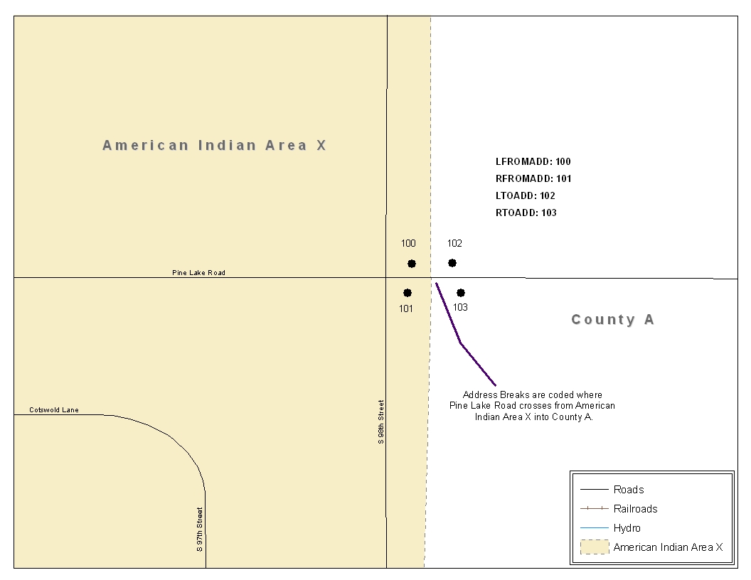
Example 6.5.1.1: This example depicts where a participant would record an address break. In the Census Bureau’s ‘Edges’ layer please be sure to fill in the correct attribute fields to show the location of the address range break. This would include the CHNG_TYPE, LTOADD, RTOADD, LFROMADD, and RFROMADD fields.
6.6 Area Landmarks, Hydro Areas, and Point Landmarks
6.6.1 Area Landmarks / Hydro Area Updates
Area landmarks and hydro areas are updated in a similar manner to boundary changes (i.e. additions, deletions, etc.). However, area landmarks and hydro areas are not legal entities. In order to submit area landmark and hydro area updates please create a separate change polygon layer. Updates that can be made to area landmarks and hydro areas include: boundary corrections (adding and removing area), creating a new area landmark or hydro area, removing an area landmark or hydro area, or changing the name. Refer to Example 6.6.1.1 for what a sample boundary correction to an area landmark would look like. Please review the example processes in Appendix 5 for information on how to create change polygons. Change polygons for area landmarks and hydro areas may be created in the same manner as additions and deletions.
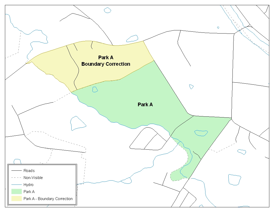
Example 6.6.1.1: This example shows an example boundary correction to Park A. Please refer to the example processes in Appendix 5 for more information on how to create change polygons for area landmark and hydro area updates. Note: While the sample processes in Appendix 5 refer to boundary changes (additions, deletions); the process to create the change polygons for area landmarks and hydro areas is the same.
Table 6.6.1.2 displays the attribute fields that are required to be filled for area landmarks and hydro areas. The change type coding scheme for area landmarks and hydro areas can be found in Appendix 4.
-Required Attributes (Area Landmark and Hydro Areas)- |
|||
|
FULLNAME |
CHNG_TYPE |
RELATE |
Boundary Correction |
X |
X |
X (IN / OUT) |
Deletion |
|
X |
|
Change Name |
X |
X |
|
New Area Landmark / Hydro Area |
X |
X |
|
Table 6.6.1.2
6.6.2 Point Landmark Updates
Updates to point landmarks may also be made. In order to submit point landmark updates, please create a separate point landmark layer with only the changes. The updates to point landmarks include: adding a new point landmark, deleting an existing point landmark, and renaming an existing point landmark. Please see Table 6.6.2.1 for the required attributes for point landmarks. In addition, the change type coding scheme for point landmarks can be found in Appendix 4.
Required Attributes (Point Landmarks) |
||
|
FULLNAME |
CHNG_TYPE |
New Point Landmark |
X |
X |
Delete Point Landmark |
|
X |
Change Name |
X |
X |
Table 6.6.2.1
6.7 Reviewing Changes to the Census Bureau Shapefiles
It is important to review the change polygon and feature layers relative to the current Census Bureau boundary and feature network. To complete this review, it is important to display the following layers of data:
Change polygon layer
Feature update layer (if one is being submitted)
Area Landmark / Hydro Area update layer (if one is being submitted)
Point Landmark update layer (if one is being submitted)
Census Bureau boundary layer (i.e. American Indian area if you are submitting change polygons for an American Indian area, or tribal subdivisions if you are submitting change polygons for a tribal subdivision)
“Edges” layer
The review of the change polygons ensures that the correct boundary-to-feature relationships are maintained in the MAF/TIGER database after changes have been made. Among other things, these boundary-to-feature relationships make certain that the appropriate population is assigned to your entity. A comprehensive review is important no matter how you choose to create change polygons. Any addition, deletion, or boundary correction must be reviewed to ensure that it is an intentional change. This review will identify any additions, deletions, and boundary corrections that do not align to the correct feature in the Census Bureau’s ‘Edges’ layer. This often occurs if there are small spatial differences between the location of your boundary in your local GIS file and the location of the feature in MAF/TIGER. Below are several examples of situations that need to be reviewed and revised prior to submission (Examples 6.7.1 - 6.7.3).
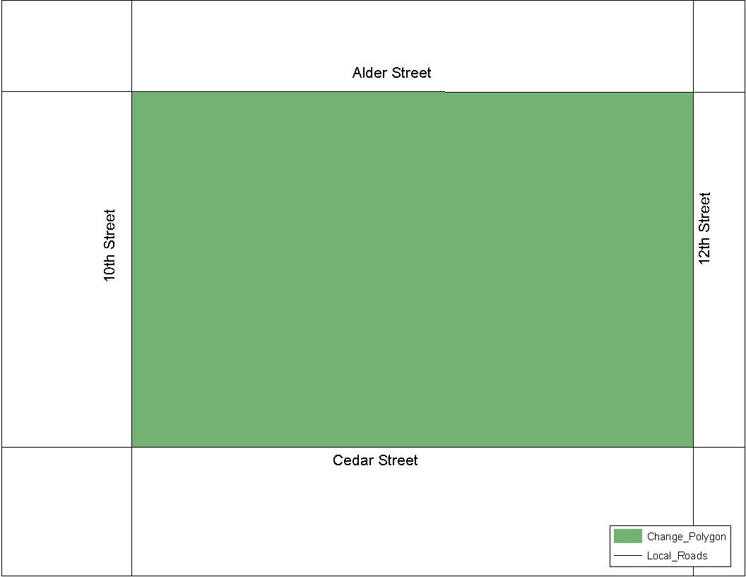
Example 6.7.1: This addition is coincident with all features in the local GIS feature and boundary files.
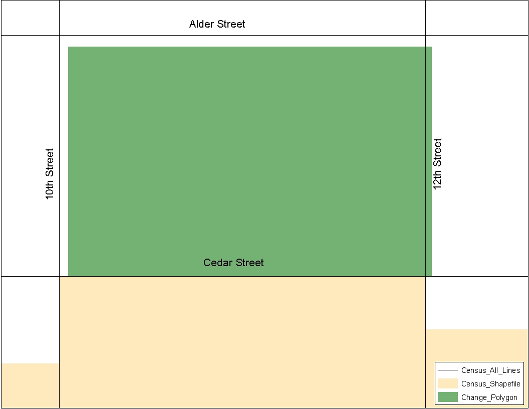
Example 6.7.2: After the change polygon is created, it is reviewed with the Census Bureau shapefiles. During this review process, it is discovered that the change polygon is not coincident with 10th, 12th, and Alder Streets in the Census Bureau shapefile.
If such spatial differences occur, and your boundary should be coincident with the centerline, snap the boundary of the change polygon to the Census Bureau feature. The Census Bureau geocodes its address, and establishes its population counts based on the centerline of a road. Snapping the change polygon to features (or creating geographic offset and corridor polygons) will ensure that the correct population is assigned to your entity.
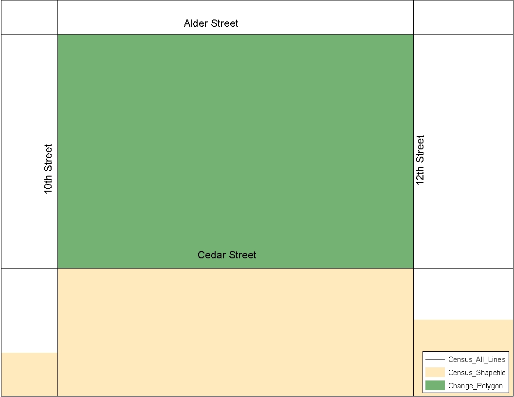
Example 6.7.3: The participant snapped the change polygon to 10th, 12th, and Alder Streets after determining that the change polygon should be coincident with them.
6.7.1 Geographic Offsets and Corridors
In some cases the boundary is not coincident with the road centerline, and a change polygon should be created and coded as either a geographic corridor or geographic offset. The Census Bureau defines a geographic offset and a geographic corridor as follows:
Geographic Offset: An area that is claimed by an entity that is only on one side of the road and does not contain any structures addressed to that side of the road
Geographic Corridor: An area that includes only road right-of-way and does not contain any structures addressed to either side of the road.
Because many entities use parcel based GIS files to maintain their boundaries, it is critical that you review your change polygons to identify situations where geographic offsets and corridors occur. If these are not identified correctly as part of your Tribal Digital BAS submission, the Census Bureau may not accurately assign the addresses to the correct geographic areas (and therefore population counts and estimates may be affected). When a geographic offset or corridor is identified please be sure to create and appropriately code change polygons to represent these offsets and corridors. For instructions on how to create geographic offset and geographic corridor change polygons you may refer to both example processes in Appendix 5. Furthermore, change type coding schemes and required attribute fields can be found in Appendix 3. Doing so will help to eliminate confusion as to where offsets and corridors occur in relation to both annexations and boundary corrections. Please refer to Examples 6.7.1.1 through 6.7.1.3 for a visual description of a geographic offset and corridor.
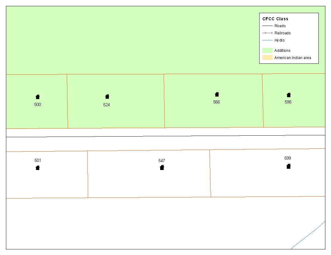
Example 6.7.1.1: This example depicts an addition made to a Census Bureau shapefile that is not coincident with the feature. This addition was created in accordance with a tribal GIS boundary file that is parcel based.
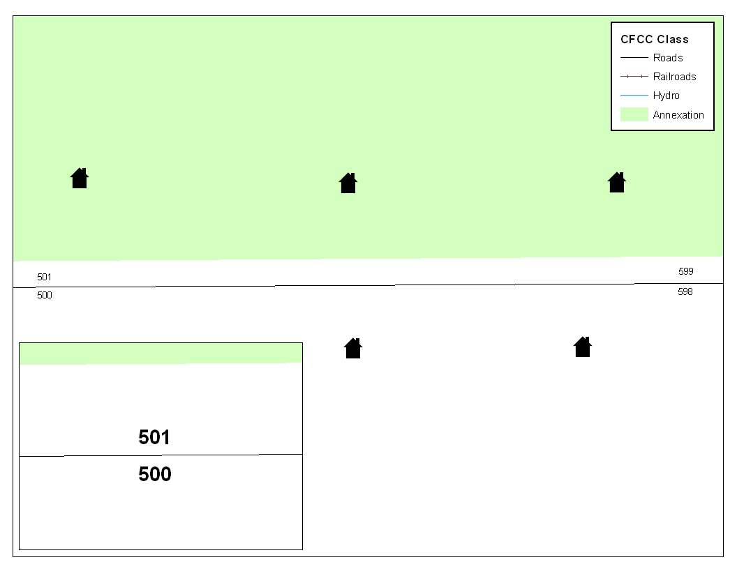
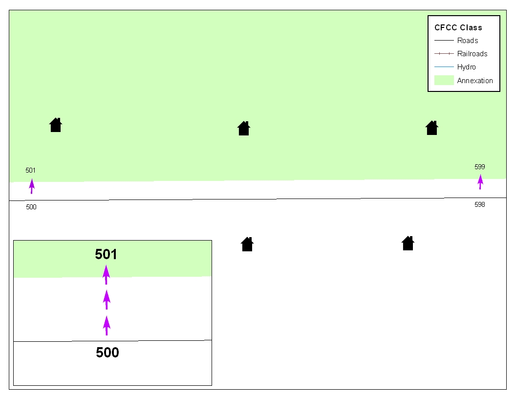
Example 6.7.1.2: The image on the left shows that the Census Bureau geocodes its addresses and establishes its population counts based on the centerline. Without creating a geographic offset polygon, the residential structures on the north side of the road will be assigned to unincorporated area rather than the tribal area to which they belong. The image on the right depicts how the Census Bureau will handle the addresses if the participant creates a geographic offset polygon. A geographic offset can be identified by creating and coding a change polygon appropriately. After creating a geographic offset change polygon, residential structures on the north side of the road would be assigned to the tribal area rather than to unincorporated area.
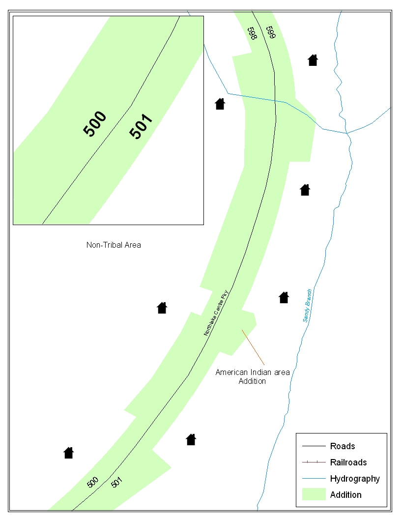
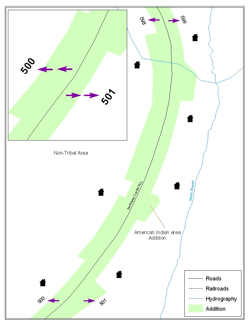
Example 6.7.1.3: The images above depict a geographic corridor. For example on the left, if no geographic corridor change polygon is created, the addresses are geocoded to the tribal area, even though the housing units are located outside of the tribal area in non-tribal area. The example on the right shows a geographic corridor polygon that is created and attributed correctly. Because of this, the addresses will be assigned to non-tribal area to match the correct location of the housing units. The residential structures and associated population are then assigned to the correct area.
6.7.2 Boundary Corrections
A thorough review of all boundary corrections also is crucial. It is especially important if the method in which you choose to extrapolate your change polygons includes overlaying the Census Bureau shapefile with the local GIS tribal boundary file. This method often creates many small sliver polygons. Oftentimes these small sliver polygons are simply a by-product of very small spatial differences.
For example, the Census Bureau boundary file and the local GIS tribal file have a boundary that runs coincident with Main Street. However, there is a spatial difference of less than ten feet between the Census Bureau and local GIS tribal boundary file. This small difference will create a very tiny sliver change polygon. This is a change polygon that you may want to delete because it will dissolve the feature to boundary relationship in MAF/TIGER. If this change were incorporated, and not identified as a geographic offset, the Census Bureau may assign the residential structures and associated population to the incorrect jurisdiction. It is also important to note that the Census Bureau will automatically snap the change polygon to the feature if the distance to that feature is less than ten feet. If the change polygon should exist within ten feet of a feature, please inform us of this.
Example 6.7.2.1 shows an instance of a small sliver boundary correction that should be deleted because it dissolves the topological relationship between a feature and boundary.

Example 6.7.2.1: This example shows boundary corrections (in green) that will dissolve the topological relationship with the road. In this instance the small sliver polygon boundary correction needs to either be deleted, or identified as a geographic offset. Dissolving the feature to boundary relationship in this scenario may affect the residential structure to tribal area relationship.
6.7.3 Linear Feature Updates
The Census Bureau also asks you to review your feature changes to ensure that all changes align with the features currently in the MAF/TIGER database. As a reminder, the Census Bureau has improved the feature network using a locally provided source to assure connectivity and topology through MTAIP (See Section 2). If your linear feature updates do not align with current MAF/TIGER linear features, the Census Bureau may not be able to incorporate the linear feature changes that you have submitted. Example 6.7.3.1 shows what you should look for when reviewing your feature changes.
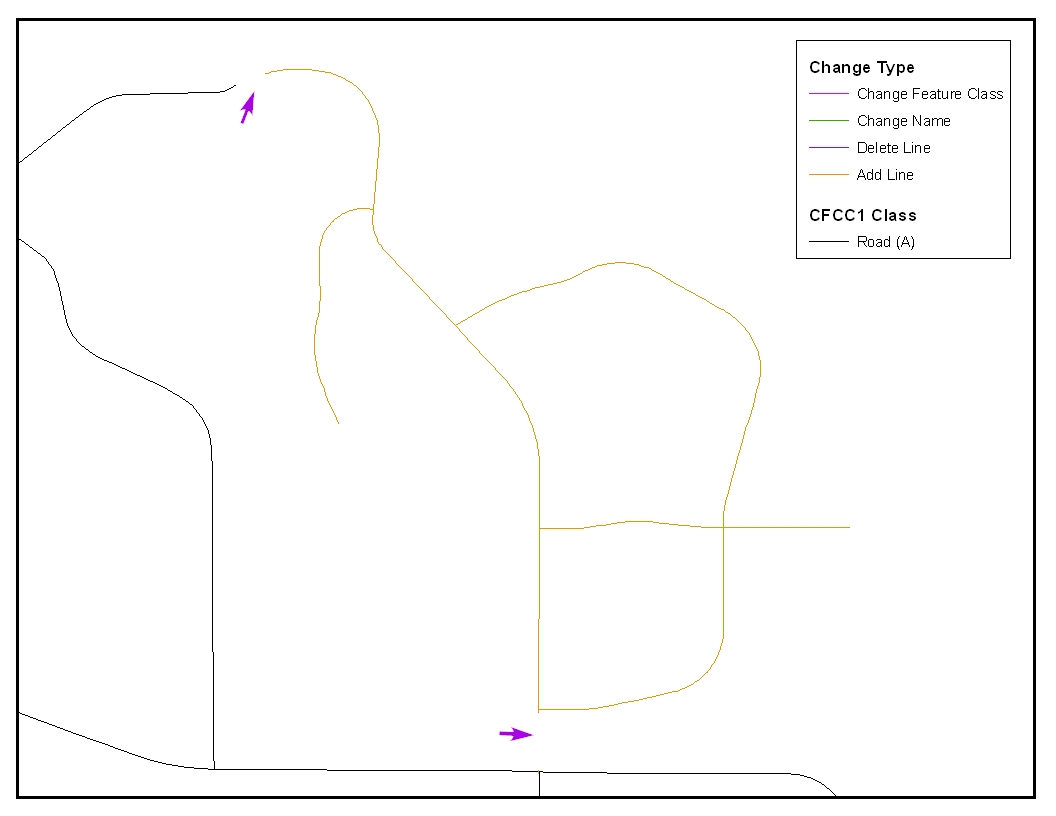
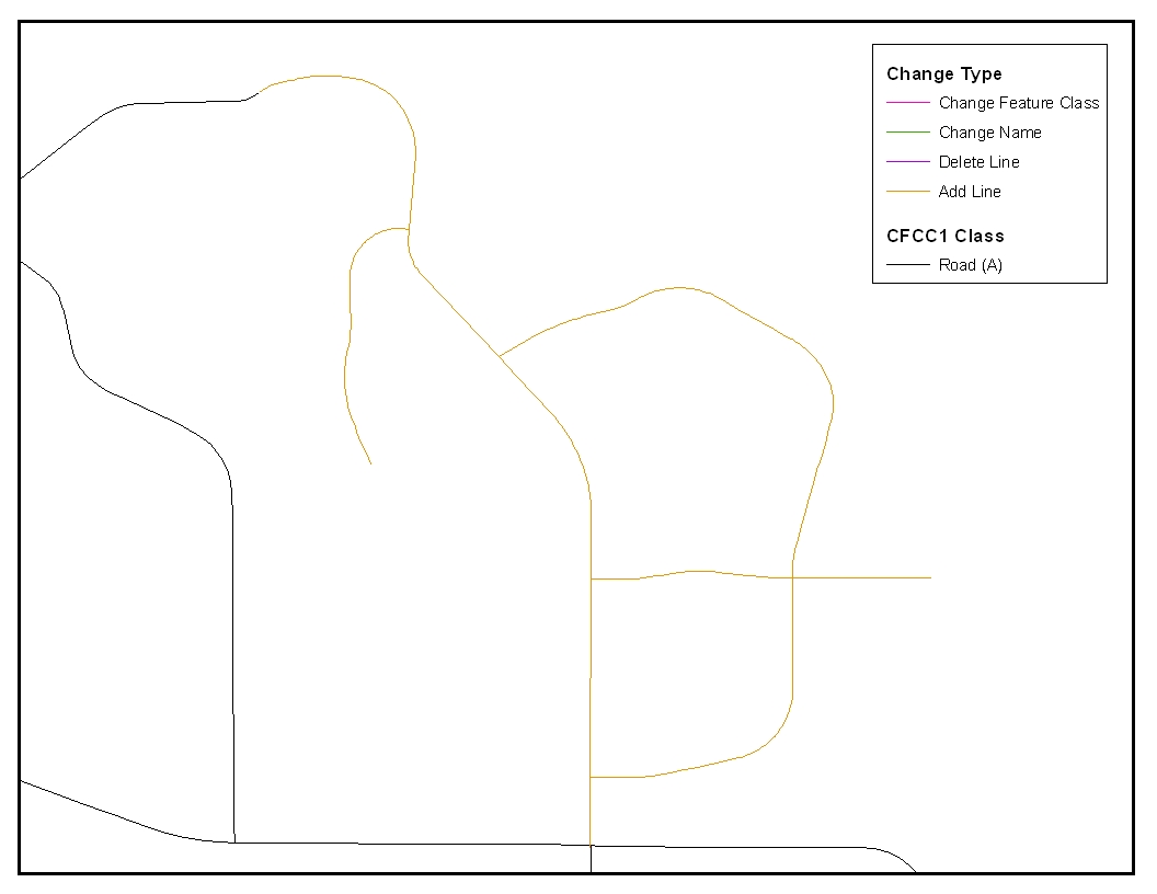
Example 6.7.3.1: The image on the left depicts a new road feature that was added to the existing feature network, but does not connect to existing road features. The image on the right shows the correction and how the new roads now connect to the existing road features.
6.7.4 Additional Review Information
The Census Bureau will not make any addition or boundary correction that affects an adjacent legal entity without confirmation from the affected entity. We ask that you please review any change polygon that affects an adjacent entity to determine if this is an intentional, legal change.
The Census Bureau also requests that you review the attribute data to ensure that the required legal documentation and change type codes are included. The list of required of change type codes are found in Appendix 3.
Again, it is important to emphasize that the Census Bureau will snap any addition, deletion, or boundary correction to a MAF/TIGER feature when it exists within ten feet of that feature. This helps to maintain the feature-to-boundary relationships in MAF/TIGER and will ensure correct housing tabulation counts for your entity.
6.8 Submitting Metadata with the Digital File
Metadata that describes the data content, coordinate system/projection, author, source, and other characteristics of GIS files is critical for Census Bureau staff to efficiently and accurately process files for Tribal Digital BAS. The Census Bureau requires that a metadata text file accompany every GIS file and layer submitted.
The Federal Geographic Data Committee’s (FGDC) Content Standard for Digital Spatial Metadata provides a national standard that enables the data-sharing public to easily locate critical information about a file and ensure that no critical information is omitted inadvertently when creating metadata. For this reason, the Census Bureau requests that metadata submitted as part of Tribal Digital BAS is submitted using this standard. For information about the FGDC and its geospatial metadata standards, please visit the following site:
http://www.fgdc.gov/metadata/metadata.html
The Census Bureau requires completion of the following sections of the FGDC metadata form:
Citation (information about the originator, publication date, title edition, and other publications or information)
Description (a section that contains an abstract describing your data set)
Time Period of Content (a section that describes the vintage of the data)
Spatial Domain (information about the bounding coordinates)
Point of Contact (general contact information about the Tribal BAS contact)
Data Quality Information (information about attribute accuracy)
Spatial Reference Information (a section on the coordinate system / projection of the data set)
Entity and Attribute Information (a section that describes the contents of your table)
To help you fulfill the requirement of filling out and submitting metadata, the Census Bureau suggests visiting the USGS Web site. This site contains useful information about the FGDC compliant metadata, from which one can read about metadata frequently asked questions, view FGDC metadata examples, and connect to other FGDC-related Web pages. For this information please visit: http://geology.usgs.gov/tools/metadata
Furthermore, if you are using ArcInfo, the FGDC link related to metadata creation tools contains a useful Arc Macro Language (AML) (i.e., fgdcmeta.aml) that when executed, completes most of the aforementioned required sections of the metadata form automatically. This AML is a product of the Illinois State Geological Survey.
http://www.FGDC.gov/metadata/toollist/fgdcmeta.html
Note: ESRI’s ArcCatalog also has an embedded program that uses the FGDC standard in its creation of geospatial metadata.
Submitting Digital Data
The Census Bureau requires that the participant submit at least two shapefiles with the potential of more. These layers are described below:
Change Polygon Layers (AIA, ANRC, Tribal Subdivisions, and Hawaiian Homelands)
These layers consist of the changes that you would like the Census Bureau to make to your entity(s).
A layer of change polygons should be created for each level of geography that changes are being created for.
Whole Modified Entity Layer (AIA, ANRC, Tribal Subdivisions, andHawaiian Homelands)
These layers should only contain the complete and current boundary for the entity being updated.
A whole entity layer should be created for each level of geography that changes are being created for.
Feature Update Layer (required only if there are feature additions, deletions, name changes, recodes, or address break changes)
If you have feature updates that you would like the Census Bureau to make, include a feature update layer with only the feature segments that you would like us to adjust.
Area Landmark Layer (required only if there are area landmark updates)
If you have area landmarks changes that you would like the Census Bureau to make, please include an area landmark update layer with only the area landmark changes that you would like us to update.
Point Landmark Layer (required only if there are point landmark updates)
If you have point landmark updates that you would like the Census Bureau to make, please include a point landmark update layer with only the point landmark changes that you would like us to update.
6.9.1 AIA, ANRC, Tribal Subdivision, and Hawaiian Homeland Submissions (Change Polygons)
Table 6.9.1.1 provides the change polygon naming conventions for AIA’s, ANRC’s and Hawaiian Homelands.
Participant |
Changes Submitted For: |
Shapefile Naming Conventions |
AIA |
AIA |
bas<yy>_<basID>_changes |
AIA |
Tribal Subdivisions |
bas<yy>_<basID>_changes_tribalsub |
ANRC |
ANRC |
bas<yy>_<basID>_changes |
Hawaiian Homelands |
Hawaiian Homelands |
bas<yy>_<basID>_changes |
Table 6.9.1.1: The table above displays the change polygons naming conventions for all participants listed above. <yy> represents the BAS year, and <basID> represents your BAS entity ID, which can be found on the CD containing your data.
6.9.2 AIA, ANRC, Tribal Subdivision, and Hawaiian Homeland Submissions (Whole Entity
Polygons)
Table 6.9.2.1 provides the whole entity polygon naming conventions for AIA’s, ANRC’s and Hawaiian Homelands.
Participant |
Changes Submitted For: |
Shapefile Naming Conventions |
AIA |
AIA |
bas<yy>_<basID>_WholeEntity |
AIA |
Tribal Subdivisions |
bas<yy>_<basID>_WholeEntity_tribalsub |
ANRC |
ANRC |
bas<yy>_<basID>_WholeEntity |
Hawaiian Homelands |
Hawaiian Homelands |
bas<yy>_<basID>_WholeEntity |
Table 6.9.2.1: The table above displays the whole entity polygon naming conventions for all participants listed above. <yy> represents the BAS year, and <basID> represents your BAS entity ID, which can be found on the CD containing your data.
6.9.3 Linear Feature, Area Landmark / Hydro Area, and Point Landmark Updates (Not
Required)
Table 6.9.3.1 provides the update layer naming conventions for the edges, area landmark, and point landmark update layer.
Participant |
Changes Submitted For: |
Shapefile Naming Conventions |
All Participants |
Edges |
bas<yy>_<basID>_LN_changes |
All Participants |
Area Landmarks |
bas<yy>_<basID>_Alndk_Changes |
All Participants |
Pont Landmarks |
bas<yy>_<basID>_Plndk_Changes |
Table 6.8.3.1: The table above displays the naming conventions for the edges, area landmark, and point landmark update layers. <yy> represents the BAS year, and <basID> represents your BAS entity ID, which can be found on the CD containing your data.
6.9.4 Compressing the Digital Files
Please compress all updates materials including: change polygon shapefiles, whole entity shapefiles, feature updates, and metadata into a single ZIP formatted file named the following:
Participant
|
Shapefile Naming Conventions |
AIA |
bas<yy>_<basID>_return
|
ANRC |
bas<yy>_<basID>_return
|
Hawaiian Homelands |
bas<yy>_<basID>_return
|
Table 6.9.4.1: The table above displays the naming conventions for the edges, area landmark, and point landmark update layers. <yy> represents the BAS year, and <basID> represents your BAS entity ID, which can be found on the CD containing your data.
6.9.5 Submitting Digital Files via File Transfer Protocol (FTP)
In order to submit your file through FTP, you must obtain the FTP address. Contact a member of the Legal Areas Team at 301-763-1099, or email [email protected] to obtain this information.
6.9.6 Additional Information
The Census Bureau recommends using FIPS codes to identify entities such as counties, minor civil divisions, and incorporated places. Using a standard coding scheme facilitates the digital exchange of data.
These codes can be obtained at: http://geonames.usgs.gov/fips55.html
If you have any questions or problems, please contact the Legal Areas Team at 301-763-1099 or email [email protected].
Appendix 1: Paperwork Reduction Project
The U.S. Census Bureau estimates that the BAS review will take most respondents from 1 to 6 hours to complete. This includes the time needed to read the instructions, assemble materials, organize and review the information, and report any needed changes. This estimate is based on 80 percent of all areas having few or no changes. However, for areas with many changes, it may take 20 hours or longer to complete the survey. Please send comments regarding this burden estimate or any other aspect of this collection of information, including suggestions for reducing this burden, to:
Paperwork Project 0607-0151
U.S. Census Bureau
4600 Silver Hill Road
Room 3K138
Washington, DC 20233
Or you may e-mail comments to:
Note: Use “Paperwork Project 0607-0151” as the subject.
Please include a copy of your message addressed to:
Appendix 2: Census Bureau Regional Offices - Contact information
|
Atlanta Regional Office 101
Marietta Street, N.W., Ste. 3200 (404) 730-3832 or (800) 424-6974 TDD: (404) 730-3964 FAX: (404) 730-3835 E-mail: |
Detroit
Regional Office (313) 259-1158 or (800) 432-1495 TDD: (313) 259-5169
Fax:
(313) 259-5045 |
|
|
Boston Regional Office 4 Copley Place, Ste. 301 P.O.
Box 9108 (617) 424-4500 or (800) 562-5721 TDD: (617) 424-0565 FAX:
(617) 424-0547 |
Kansas
City Regional Office (913) 551-6728 or (800) 728-4748 TDD: (913) 551-5839
Fax:
(913) 551-6789 |
|
|
Charlotte
Regional Office (704) 424-6400 or (800) 331-7360 TDD: (704) 344-6114 Fax:
(704) 424-6944 |
Los
Angeles Regional Office (818) 267-1700 or (800) 992-3530
TDD:
(818) 904-6249 |
|
|
Chicago
Regional Office Oak Brook, IL 60523-1918 (630)
288-9200 or (800) 865-6384 |
New
York Regional Office New York, NY 10014 (212) 584-3400 or (800) 991-2520 TDD: (212) 478-4793 Fax: (212) 478-4800 E-mail: |
|
|
Dallas
Regional Office Dallas, TX 75247 (214) 253-4401 or (800) 835-9752 TDD:
(214) 655-5363 |
Philadelphia
Regional Office (215) 717-1800 or (800) 262-4236 TDD: (215) 717-0894
Fax:
(215) 717-0755 |
|
|
Denver
Regional Office (303) 264-0202 or (800) 852-6159 TDD:
(303) 969-6767 |
Seattle
Regional Office (206)
381-6200 or (800) 233-3308 Fax
(206) 381-6310 |
|
Appendix 3 – Required Fields and Coding Scheme
-Required Attributes (Change Polygons)- |
|||||||
|
NAME |
CHNG_TYPE |
EFF_DATE |
DOCU |
OFFSET |
AREA |
RELATE |
Addition |
X |
X |
X |
X |
|
|
|
Deletion |
X |
X |
X |
X |
|
|
|
Boundary Correction |
X |
X |
|
|
|
|
X (IN / OUT) |
Geographic Offset |
|
X |
|
|
X |
|
|
Geographic Corridor |
|
X |
|
|
X |
|
|
New Entity |
X |
X |
X |
X |
|
|
|
-Required Attributes (Linear Feature Updates)- |
|||||||
|
CHNG_TYPE |
FENAME |
MTFCC |
LTOADD |
RTOADD |
LFROMADD |
RFROMADD |
Add Feature |
X |
X |
X |
|
|
|
|
Delete Feature |
X |
|
|
|
|
|
|
Rename Feature |
X |
X |
|
|
|
|
|
Recode Feature (MTFCC) |
X |
|
X |
|
|
|
|
Address Break Updates |
X |
|
|
X |
X |
X |
X |
-Required Attributes (Area Landmark and Hydro Areas)- |
|||
|
FULLNAME |
CHNG_TYPE |
RELATE |
Boundary Correction |
X |
X |
X |
Deletion |
|
X |
|
Change Name |
X |
X |
|
New Area Landmark / Hydro Area |
X |
X |
|
-Required Attributes (Point Landmarks)- |
||||
|
FULLNAME |
CHNG_TYPE |
||
New Point Landmark |
X |
X |
||
Delete Point Landmark |
|
X |
||
Change Name |
X |
X |
||
-Change Type Codes for Boundary Updates- |
|
|||
CHNG_TYPE |
TRANSLATION |
|
||
A |
Addition |
|
||
B |
Boundary Correction |
|
||
C |
Geographic Corridor |
|
||
D |
Deletion |
|
||
E |
New Entity |
|
||
F |
Geographic Offset |
|
||
-Change Type Codes for Feature Updates- |
|
CHNG_TYPE |
TRANSLATION |
AL |
Add Feature |
DL |
Delete Feature |
CA |
Change Feature Name |
CA |
Change Feature Class |
CA |
Add Address Break |
-Change Type Codes for Area Landmarks and Hydro Areas- |
|
CHNG_TYPE |
TRANSLATION |
D |
Deletion |
B |
Boundary Corrections |
E |
New Area Landmark / Hydro Area |
G |
Name Change |
-Change Type Codes for Point Landmarks- |
|
CHNG_TYPE |
TRANSLATION |
D |
Deletion |
E |
New Point Landmark |
G |
Name Change |
Appendix 4 – Data Dictionary
-Alaska Native Regional Corporation (ANRC) Shapefile- |
|||
ATTRIBUTE FIELD |
LENGTH |
TYPE |
DESCRIPTION |
STATEFP |
2 |
String |
FIPS State Code |
COUNTYFP |
3 |
String |
FIPS County Code |
ANRCFP |
5 |
String |
FIPS ANRC Code |
ANRCCE |
2 |
String |
Current Census ANRC Code |
NAME |
100 |
String |
ANRC Name |
NAMELSAD |
120 |
String |
Name with Translated LSAD |
LSAD |
2 |
String |
Legal / Statistical Area Description |
AIANNHNS |
8 |
String |
ANSI Numeric Indentifier for AIANNH Areas |
FUNCSTAT |
1 |
String |
Functional Status |
CLASSFP |
2 |
String |
FIPS 55 Class Code Describing an Entity |
PARTFLG |
1 |
String |
Part Flag Indicator |
CHNG_TYPE |
2 |
String |
Type of Area Update |
EFF_DATE |
8 |
String |
Effective Date |
DOCU |
120 |
String |
Supporting Documentation |
FORM_ID |
4 |
String |
(MTPS and Web BAS Only) |
AREA |
10 |
Double |
Acreage of Area Update |
RELATE |
120 |
String |
Relationship Description |
VINTAGE |
2 |
String |
Vintage of the Data |
AIANNHFSR |
1 |
String |
Flag Indicating Level of Recognition of an AIA |
-American Indian Areas (AIA) Shapefile- |
|||
ATTRIBUTE FIELD |
LENGTH |
TYPE |
DESCRIPTION |
STATEFP |
2 |
String |
FIPS State Code |
COUNTYFP |
3 |
String |
FIPS County Code |
AIANNHCE |
4 |
String |
Census AIANNH Code |
COMTYP |
1 |
String |
Indicates if Reservation, Off-Reservation Trust Land, or both are Present |
AIANNHFSR |
1 |
String |
Flag Indicating Level of Recognition of an AIA |
AIANNHNS |
8 |
String |
ANSI Numeric Identifier for AIANNH Areas |
NAME |
100 |
String |
AIA Name |
NAMELSAD |
120 |
String |
Name with Translated LSAD |
LSAD |
2 |
String |
Legal / Statistical Area Description |
FUNCSTAT |
1 |
String |
Functional Status |
CLASSFP |
2 |
String |
FIPS 55 Class Code Describing an Entity |
PARTFLG |
1 |
String |
Part Flag Indicator |
CHNG_TYPE |
2 |
String |
Type of Area Update |
EFF_DATE |
8 |
String |
Effective Date |
DOCU |
120 |
String |
Supporting Documentation |
FORM_ID |
4 |
String |
(MTPS and Web BAS Only) |
AREA |
10 |
Double |
Acreage of Area Update |
RELATE |
120 |
String |
Relationship Description |
VINTAGE |
2 |
String |
Vintage of the Data |
-American Indian Tribal Subdivisions (AITS) Shapefile- |
|||
ATTRIBUTE FIELD |
LENGTH |
TYPE |
DESCRIPTION |
STATEFP |
2 |
String |
FIPS State Code |
COUNTYFP |
3 |
String |
FIPS County Code |
AIANNHCE |
4 |
String |
Census AIANNH Code |
TRIBALSUBCE |
1 |
String |
Census Tribal Subdivision Code |
AIANNHFSR |
1 |
String |
Flag Indicating Level of Recognition of an AIA |
AIANNHNS |
8 |
String |
ANSI Numeric Identifier for AIANNH Areas |
NAME |
100 |
String |
AIA Name |
NAMELSAD |
120 |
String |
Name with Translated LSAD |
LSAD |
2 |
String |
Legal / Statistical Area Description |
FUNCSTAT |
1 |
String |
Functional Status |
CLASSFP |
2 |
String |
FIPS 55 Class Code Describing an Entity |
PARTFLG |
1 |
String |
Part Flag Indicator |
CHNG_TYPE |
2 |
String |
Type of Area Update |
EFF_DATE |
8 |
String |
Effective Date |
DOCU |
120 |
String |
Supporting Documentation |
FORM_ID |
4 |
String |
(MTPS and Web BAS Only) |
AREA |
10 |
Double |
Acreage of Area Update |
RELATE |
120 |
String |
Relationship Description |
VINTAGE |
2 |
String |
Vintage of the Data |
-Edges Shapefile- |
|||
ATTRIBUTE FIELD |
LENGTH |
TYPE |
DESCRIPTION |
TLID |
10 |
Integer |
Permanent Edge ID |
STATEFPL |
2 |
String |
State FIPS Code (Left) |
STATEFPR |
2 |
String |
State FIPS Code (Right) |
COUNTYFPL |
3 |
String |
County FIPS Code (Left) |
COUNTYFPR |
3 |
String |
County FIPS Code (Right) |
TFIDL |
10 |
Integer |
Permanent Face ID (Left) |
TFIDR |
10 |
Integer |
Permanent Face ID (Right) |
MTFCC |
5 |
String |
MAF/TIGER Feature Class Code |
FIDELITY |
1 |
String |
Indication to a respondent when their entity boundary has changed through spatial enhancement |
FULLNAME |
120 |
String |
Prefix qualifier code, prefix direction code, prefix type code, base name, suffix type code, suffix qualifier code |
BBSPFLG |
1 |
String |
Redistricting data project participant’s submitted request of an EDGE for selection as a block boundary |
CBBFLG |
1 |
String |
Indicates the status of an EDGE for a selection as a block boundary |
2010_BBSP |
1 |
String |
New BBSP flag |
CHNG_TYPE |
2 |
String |
Type of linear update |
LTOADD |
10 |
String |
Left To Address |
RTOADD |
10 |
String |
Right To Address |
LFROMADD |
10 |
String |
Left From Address |
RFROMADD |
10 |
String |
Right From Address |
ZIPL |
5 |
String |
Left Zip Code |
ZIPR |
5 |
String |
Right Zip Code |
-Area Landmark Shapefile- |
|||
ATTRIBUTE FIELD |
LENGTH |
TYPE |
DESCRIPTION |
STATEFP |
2 |
String |
FIPS State Code |
COUNTYFP |
3 |
String |
FIPS County Code |
MTFCC |
5 |
String |
MAF/TIGER Feature Class Code |
FULLNAME |
120 |
String |
Prefix direction code, prefix type code, base name, suffix type code, suffix direction code |
AREAID |
10 |
Integer |
Landmark identification number |
ANSICODE |
8 |
String |
ANSI code for area landmarks |
CHNG_TYPE |
1 |
String |
Type of Area Landmark update |
EFF_DATE |
8 |
String |
Effective Date or Vintage |
RELATE |
120 |
String |
Relationship description |
BAG |
3 |
String |
Block Area Grouping |
-Hydro Area Shapefile- |
|||
ATTRIBUTE FIELD |
LENGTH |
TYPE |
DESCRIPTION |
STATEFP |
2 |
String |
FIPS State Code |
COUNTYFP
|
3 |
String |
FIPS County Code |
ANSICODE |
8 |
String |
ANSI code for hydrography area |
MTFCC |
5 |
String |
MAF/TIGER Feature Class Code |
FULLNAME |
120 |
String |
Prefix direction code, prefix type code, base name, suffix type, suffix type code, suffix direction code |
CHNG_TYPE |
1 |
String |
Type of Area Update |
HYDROID |
10 |
String |
Hydrography Identification Number |
-Point Landmarks Shapefile- |
|||
ATTRIBUTE FIELD |
LENGTH |
TYPE |
DESCRIPTION |
STATEFP |
2 |
String |
FIPS State Code |
COUNTYFP
|
3 |
String |
FIPS County Code |
POINTID |
10 |
Integer |
Point Landmark Identification Number |
MTFCC |
5 |
String |
MAF/TIGER Feature Class Code |
FULLNAME |
120 |
String |
Prefix type code, base name, suffix type code |
CHNG_TYPE |
1 |
String |
Type of Area Update |
Appendix 5 – ArcGIS Example Processes 1 & 2
-Outline – Example Process 1-
Copy the Census Bureau shapefiles to your computer or server.
Open the following files in your GIS:
DB07_<ST><COU>_AIA
DB07_<ST><COU>_AllLines
Display all Roads, Railroads, Hydrography, and Non-visible Features using the CFCC1 code. Listed below is the recommended symbology and coloring scheme.
A: Roads – solid black line
B: Rail – hatched brown line
F: Non-visible Features – light gray, dashed line
H: Hydrography – solid blue line
Create change polygons using the following methods:
Using ArcGIS’s ‘Select Feature’ tool, select already existing lines from the Census Bureau’s ‘Edges’ layer. If a line does not already exist in the ‘Edges’ layer, create a new line using editing tools in ArcGIS. Also, lines that need to be split can be split using the ‘Split’ lines tool in ArcGIS with help from snapping in the Editor toolbar.
After edges that comprise a single change polygon (or multiple change polygons) have been selected, export the selected features into a new feature layer.
After all features have been exported for each change polygon, use the ‘Feature to Poly’ tool in ArcGIS to create the change polygons.
Add required fields to the attribute table. Detailed instructions for this step can be found in Sample Process 1. After adding the required fields, these fields should be populated with the appropriate attribute information.
Review each of the change polygons in accordance with the guidelines described in Section 5.6. Note: If you are editing multiple levels of geography (i.e. American Indian areas and tribal subdivisions), please be sure to create a separate change polygon layer for each.
Review Section 5.8 to determine proper naming conventions for shapefiles. Please zip the shapefiles together (Section 5.8.4) and FTP to the Census Bureau (Section 5.8.5).
Review Example Process 1 for Detailed Procedures
-Outline – Example Process 2-
Copy the Census Bureau shapefiles from the CD to your computer or server.
Open the following files in your GIS:
DB07_<ST><COU>_AIA
DB07_<ST><COU>_AllLines
Display all Roads Railroads, Hydrography, and Invisible Features using the CFCC1 code. Listed below is the recommended symbology and coloring scheme.
A: Roads – solid black line
B: Rail – hatched brown line
F: Invisible Features – light gray, dashed line
H: Hydrography – solid blue line
Overlay your local GIS tribal boundary file with the Census Bureau boundary file.
Use the ‘Symmetrical Difference’ tool in ArcGIS to create change polygons using the Census Bureau’s boundary file and your local GIS boundary file.
If necessary create change polygons for any geographic offsets or corridors that are necessary for additions, deletion, or boundary corrections. Merge this layer with the change polygon layer.
Populate the required BAS-related fields in the change polygon attribute table. The change polygon coding scheme can be found in Appendix B. Please be sure to include only the fields listed in Section 5.6.
Review each of the change polygons in accordance with the guidelines described in Section 5.6. Note: If you are editing multiple levels of geography (i.e. American Indian areas and tribal subdivisions), please be sure to create a separate change polygon layer for each.
Review Section 5.8 to determine proper naming conventions for shapefiles. Please zip the shapefiles together (Section 5.8.4) and FTP to the Census Bureau (Section 5.8.5)
Review Example Process 2 for Detailed Procedures
2007 Tribal Digital BAS – Example Process 1
-Selecting Lines to Form Change Polygons-
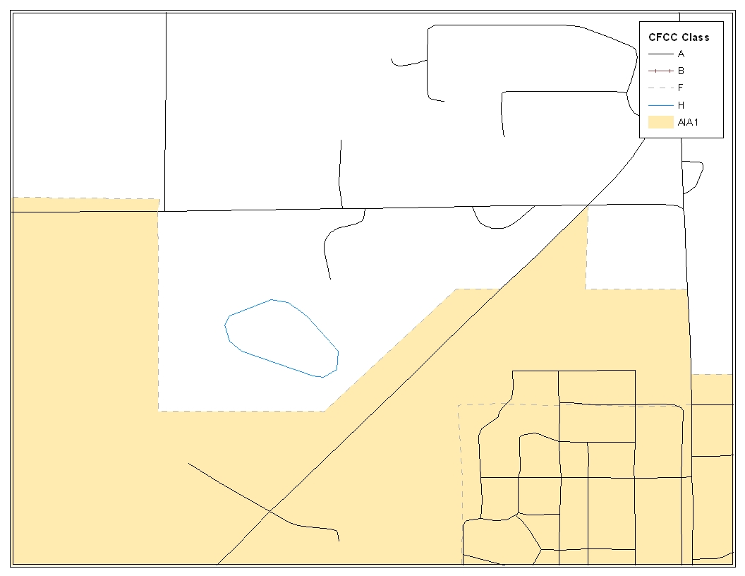
Image 1.1
Opening Census Bureau Shapefiles: Image 1.1 shows the original Census Bureau shapefiles that you will be receiving for editing in Tribal Digital BAS. Because this example is at the American Indian area layer, the DB07_<ST><COU>_AIA layer should be opened. In order to create change polygons by selecting lines it is also very important to have the DB07_<ST><COU>_AllLines shapefile open. The Census Bureau suggests that four CFCC1 values be displayed for selecting lines to create change polygons. These values include A (roads), B (railroads), F (invisible), and H (hydrography). The image above can be used as a guide for the most effective symbolization methods.
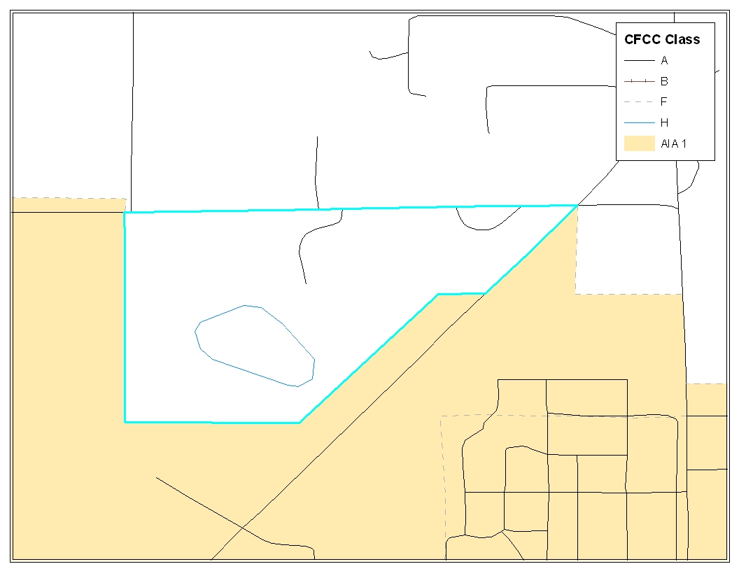
Image 1.2
Selecting
Lines from Existing Features in the Edges Layer:
In order to create change polygons, lines must be selected from the
‘Edges’ layer. In this image, each line can be selected
from existing lines in the ‘Edges’ layer using the
‘Select Features’ tool.
![]() When selecting lines please be sure to choose the ‘Selection’
tab at the bottom of the Table of Contents (ArcGIS), and check only
the ‘Edges’ layer.
When selecting lines please be sure to choose the ‘Selection’
tab at the bottom of the Table of Contents (ArcGIS), and check only
the ‘Edges’ layer.
![]() In this simple situation, there are no lines that need to be added
or split in the ‘Edges’ layer. Image 1.3 will cover how
to create, split, and select lines for creating additional change
polygons.
In this simple situation, there are no lines that need to be added
or split in the ‘Edges’ layer. Image 1.3 will cover how
to create, split, and select lines for creating additional change
polygons.
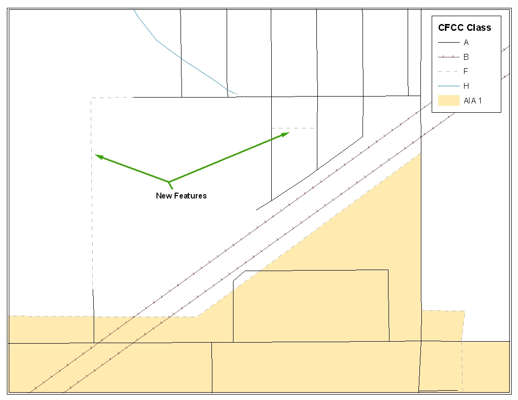
Image 1.3
Creating New Features to Form an Addition: When creating change polygons there are many situations where lines need to be created so that they may be selected and converted into a polygon. It is best to make a copy of the DB07_<ST><COU>_AllLines layer so that the original may be used for feature changes in a later process.
![]()
Image 1.4
In
ArcGIS, use the Editor Tool (Image 1.4) to create new features that
can be selected to form new polygons. In the ‘Task’
dropdown select Create New Feature and in the Target dropdown select
the copied version of the ‘Edges’ layer. In the Editor
Toolbar set the snapping to vertex, edge, and end,
![]() and begin creating features using the Pencil tool shown above.
and begin creating features using the Pencil tool shown above.
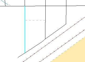
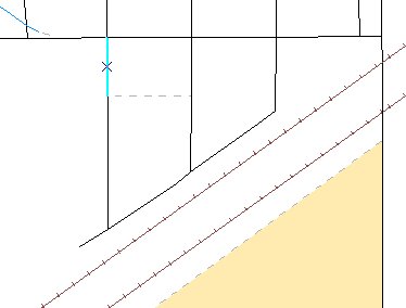
It
may also be necessary to split lines to select the appropriate
features for creating change polygons. With snapping set, the Manual
Split tool
![]() can be used to split an existing feature at the intersection point
with the new feature. Then the appropriate lines can be selected to
create polygons.
can be used to split an existing feature at the intersection point
with the new feature. Then the appropriate lines can be selected to
create polygons.
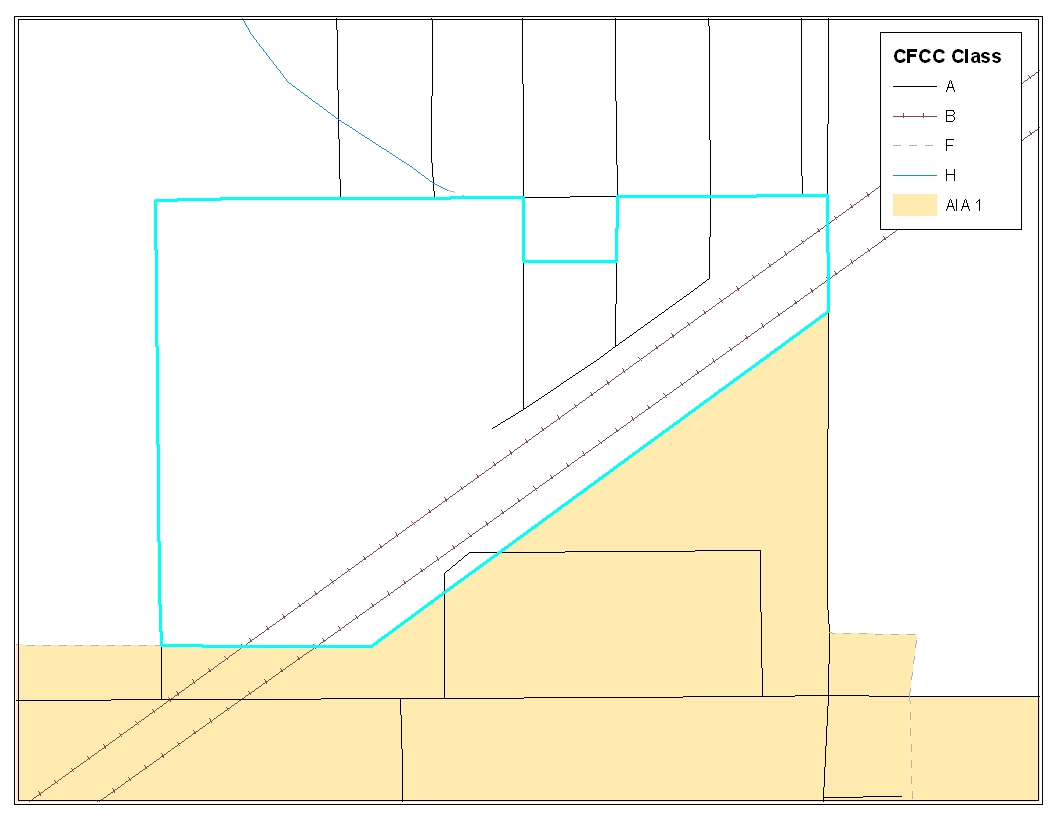
Image 1.5
Constructing Change Polygons: After creating, splitting, and selecting both new and existing features, a change polygon (Image 1.5) can be created from these selected features. After selecting all the appropriate features from the ‘Edges’ layer for a change polygon, the selected lines must be exported to a new layer so that they may be converted to a polygon shapefile (Note: You may choose to export selected lines individually or as a whole).
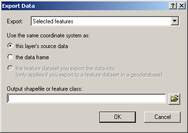
Image 1.6
After selecting all the appropriate features from the ‘Edges’ layer for a change polygon, the selected lines must be exported to a new layer (Image 1.6) so that they may be converted to a polygon shapefile.

Image 1.7
Creating
Polygons From Features:
After creating and exporting all features for additions, deletions,
and boundary corrections use the ‘Feature to Polygon’
tool (Image 1.7) in ArcToolbox.
![]() Each set of features that were earlier selected and exported to a
new layer can be put into the ‘Feature to Polygon’ tool
to create a change polygon layer.
Each set of features that were earlier selected and exported to a
new layer can be put into the ‘Feature to Polygon’ tool
to create a change polygon layer.
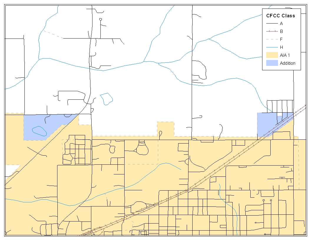
Image 1.8
Creating and Attributing Change Polygons: After creating a change polygon layer, the attribute table must be updated to reflect information that is required by the Census Bureau.
W hen
change polygons are created the attribute table only contains three
fields (FID, Shape, ID). The Census Bureau requires that six
additional fields be added (AIA Name, Change Type, Legal
Documentation, Effective Date, Offset, and Area). Table A provides
additional information.
Name |
Attribute Table Name |
Character Type |
Length |
AIA Name |
AIA_name |
Text |
50 |
Change Type |
Chng_Type |
Text |
1 |
Legal Documentation |
Legal_doc |
Text |
20 |
Effective Date |
Eff_date |
Text |
10 |
Offset |
Offset |
Text |
10 |
Area |
Area |
Double |
10 |
Table A
![]()
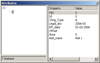
In
order to populate the required field in the attribute table, the
Editor Toolbar is again necessary. After Start Editing is selected,
select your change polygon layer as the Target. Using the Edit Tool
![]() select a change polygon and add attribute information by pressing the
Attributes button.
select a change polygon and add attribute information by pressing the
Attributes button.
![]() (Image 1.9) This step must be completed for each change polygon that
you have created.
(Image 1.9) This step must be completed for each change polygon that
you have created.
Image 1.9
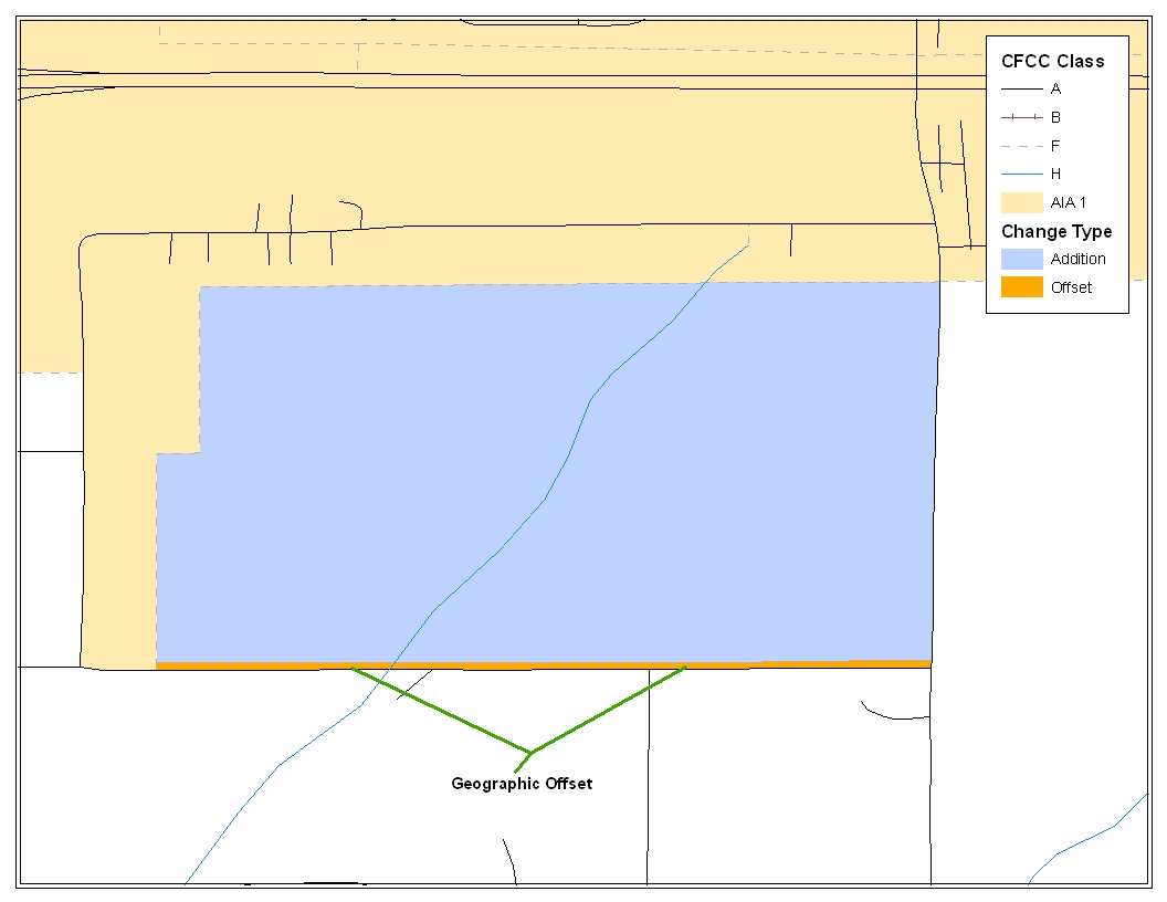
Image 1.10
Addition with Geographic Offset (Image 1.10): Often times change polygons are created that have geographic offsets or corridors. Like previous change polygons, participants are asked to create, split, and select lines to form change polygons. In addition, the Census Bureau requests that you create a change polygon for the geographic offset and code it with the appropriate coding scheme.
Geographic Offset / Corridor Change Polygon: A separate change polygon should be created whenever a geographic offset or corridor is necessary. These change polygons can be created using similar methods to those shown for creating and coding addition polygons. The only attribute information for geographic offset and corridor polygons are change type and American Indian area name. (Geographic Offset – F and Geographic Corridor – C)
![]()
B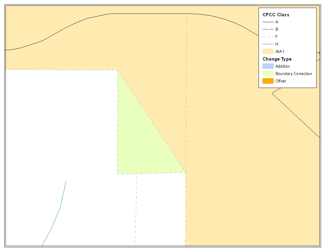 oundary
Correction Change Polygons (Image 1.11):
In addition to additions or deletions, your entity may have boundary
corrections that it wishes to make. Change polygons for boundary
corrections can be created and coded using the same techniques for
creating addition polygons. The only attribute information required
for boundary corrections are change type and AIA name.
Image 1.11
![]()
F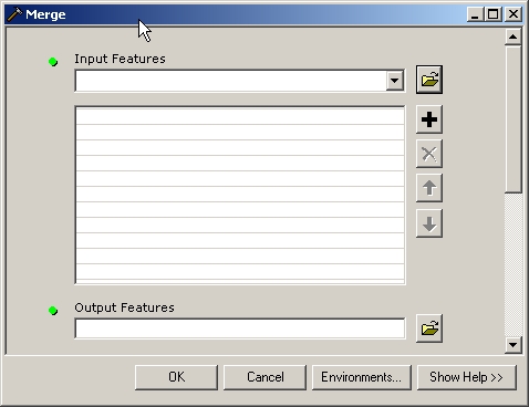 orming
a Single Change Polygon Layer: When
all change polygons have been created, (additions, deletions,
boundary corrections, offsets, and corridors) they should be merged
into a single change polygon layer for each level of geography and
named:
AIA DB07_<ST><COU>_Changes_AIA
AITLI DB07_<ST><COU>_Changes_AITLI
AITS DB07_<ST><COU>_Changes_AITS
Using the ‘Merge’ tool (Image 1.12) in ArcGIS will allow you to enter any number of change polygon layers as an input and receive a single change polygon layer as an output.
Image 1.12
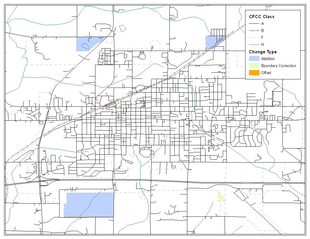
Image 1.13

Image 1.14
After finalizing your change polygons and attribute table, the Census Bureau requests that you review your change polygons to ensure that these are changes you intend on making, and that these changes contain the required attribute data (Image 1.13 and 1.14). Section 5.6 describes, in depth, how to review your change polygons.
2007 Tribal Digital BAS – Example Process 2
-Overlaying Census and American Indian Area Shapefiles to Form Change Polygons-
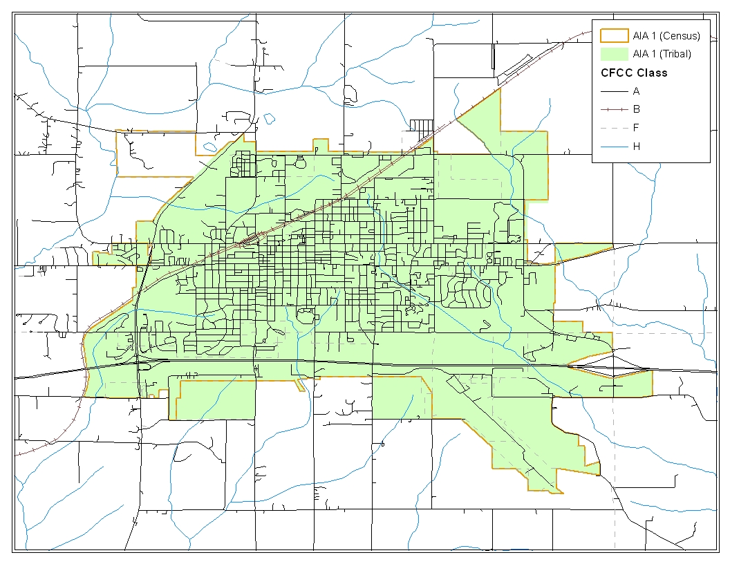
Image 2.1
Opening Census Bureau and Local Tribal Shapefiles: This example provides a process that could be used to overlay the Census Bureau and local GIS American Indian area shapefiles. Because this example is at the American Indian area layer, the DB07_<ST><COU>_AIA layer should be opened. In addition, your local GIS American Indian area layer should be opened for the comparison and overlay process.
For reference it is also important to have the DB07_<ST><COU>_AllLines layer open. The Census Bureau suggests that four CFCC1 values be displayed for selecting lines to create change polygons. These values include A (roads), B (railroads), F (invisible), and H (hydrography).
Image 2.1 shows the differences between the Census Bureau and tribal area. These differences will be the ones extrapolated as changes for the change polygon layer.
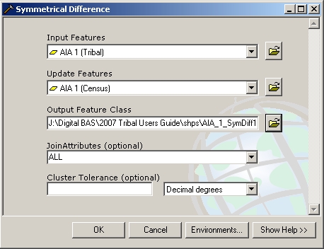
Image 2.1
Overlay the Census Bureau and American Indian Area Layers: The differences between the Census Bureau and American Indian area layers can be found using the ‘Symmetrical Difference’ overlay tool (Image 2.2) in ArcGIS. The ‘Input Features’ and ‘Update Features’ dialog in the tool can be populated by either the local or Census Bureau American Indian area layer. Which layer goes in which dialog is not important. This process creates a change polygon layer with one record for all of the changes that have been made. It is important that this record is split so that each individual polygon has its own unique record in the attribute table.

Image 2.3
Splitting Change Polygons for Individual Records: It is important that each has its own record in the attribute table. The ‘Multipart To Singlepart’ tool (Image 2.3) in ArcGIS allows you to split the polygons so that each has its own record in the attribute table. The change polygons can then be coded appropriately.
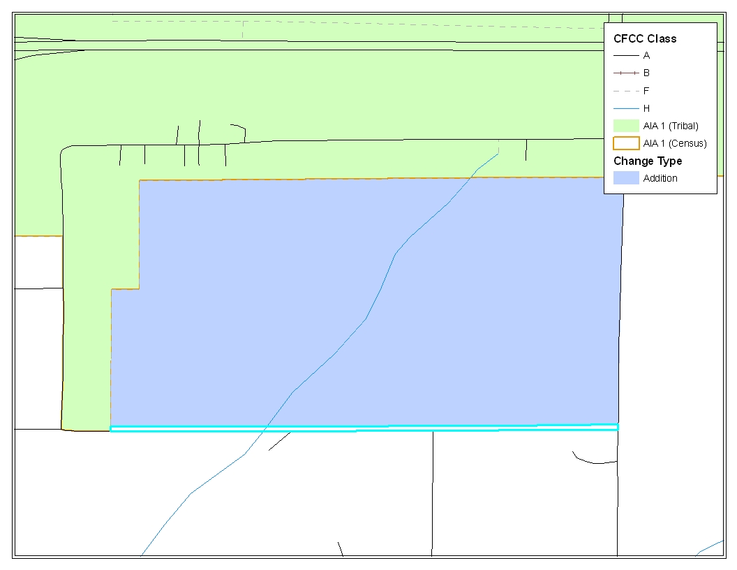
Image 2.4
Creating Geographic Offset and Corridor Polygons: A geographic offset or corridor change polygon is necessary wherever an offset or corridor should exist. Section 5.6.1 provides definitions of both geographic offsets and corridors.
Selecting
Features to Form Geographic Offset / Corridor Polygons:
In order to create change polygons, lines must be selected from the
‘Edges’ layer. In image 2.4, each line can be selected
from existing lines in the ‘Edges’ layer using the
‘Select Features’ tool.
![]() When selecting lines please be sure to select the ‘Selection’
tab at the bottom of the Table of Contents (ArcGIS) and check only
the ‘Edges’ layer.
When selecting lines please be sure to select the ‘Selection’
tab at the bottom of the Table of Contents (ArcGIS) and check only
the ‘Edges’ layer.
![]() In this simple situation, there are no lines that need to be added
or split in the ‘Edges’ layer. If lines need to be added
or split, utilize the sketch tool
In this simple situation, there are no lines that need to be added
or split in the ‘Edges’ layer. If lines need to be added
or split, utilize the sketch tool
![]() and the split line tool.
and the split line tool.
![]()
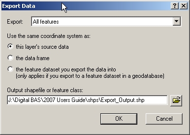
Image 2.5
Exporting Selected Features (Image 2.5): After selecting all the appropriate features from the ‘Edges’ layer for an offset polygon, the selected lines must be exported to a new layer so that they may be converted to a polygon shapefile. You may select and export all line features for offsets and corridors individually or all together (if you have more than one offset or corridor).

Image 2.6
Converting
Features to Polygons:
After creating and exporting all features for geographic offsets and
corridors use the ‘Feature to Polygon’ tool (Image 2.6)
in ArcToolbox.
![]() Each set of features that were earlier selected and exported to a
new layer can be put into the ‘Feature to Polygon’ tool
to create an offset and corridor polygon layer.
Each set of features that were earlier selected and exported to a
new layer can be put into the ‘Feature to Polygon’ tool
to create an offset and corridor polygon layer.

Image 2.7
Merging the Offset / Corridor Polygons with Change Polygon Layer (Image 2.7): After creating polygons for offsets and corridors, it is important to merge these polygons with your addition, deletion, and boundary correction layer. Please create separate change polygon layers for each level of geography that you edit (i.e. AIA, AITLI, and AITS) using the naming conventions below:
AIA DB07_<ST><COU>_Changes_AIA
AITLI DB07_<ST><COU>_Changes_AITLI
AITS DB07_<ST><COU>_Changes_AITS
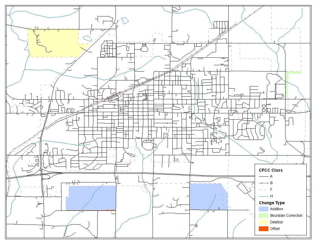
Image 2.8

Image 2.9
Updating the Attribute Table (Image 2.8 and 2.9): Information for coding the attribute table with the appropriate change types can be found in Appendix B. In addition, Section 5.3 and Appendix B detail the fields that are required to be populated for additions, deletions, boundary corrections, offsets and corridors.
After finalizing your change polygons and attribute table, the Census Bureau requests that you review your change polygons to ensure that these are changes you intend on making, and that these changes contain the required attribute data. When using this method to update your boundaries there are often small spatial corrections between the local file and the Census Bureau shapefile. These changes may dissolve a topological relationship between a road feature and a boundary which potentially could affect population counts. Please review Section 5.6 for information on how to adequately review your change polygons.
1 The use of brand names does not represent an endorsement of a company or its products by the U.S. government. Due to the wide use of ESRI products by our partners in the GIS community, and the ubiquitous use of the shapefile format as a medium for GIS data exchange, the Census Bureau is providing this data in shapefile format. You should encounter no problems when importing these shapefiles into your local GIS software. However, if you are using GIS software that does not contain a shapefile translator, please contact the Census Bureau for further instructions (301-763-1099 or e-mail [email protected]).
2 Only new tribal subdivisions can be created as new entities.
| File Type | application/msword |
| Author | cleme309 |
| Last Modified By | Bureau Of The Census |
| File Modified | 2007-05-15 |
| File Created | 2006-09-29 |
© 2026 OMB.report | Privacy Policy
 ppendix
5