SFAR- Mitsubishi MU-2B Series Airplane Special Training, Experience, and Operating Procedures
SFAR- Mitsubishi MU-2B Series Airplane Special Training, Experience, and Operating Procedures
Special Federal Aviation Regulation No 108
SFAR- Mitsubishi MU-2B Series Airplane Special Training, Experience, and Operating Procedures
OMB: 2120-0725
Special Federal Aviation Regulation No. 108—Mitsubishi MU–2B Series Special Training, Experience, and Operating Requirements
1. Applicability. After February 5, 2009, this Special Federal Aviation Regulation (SFAR) applies to all persons who operate the Mitsubishi MU–2B series airplane including those who act as pilot-in-command, act as second-in-command, or other persons who manipulate the controls while under the supervision of a pilot-in-command. This SFAR also applies to those persons who provide pilot training for the Mitsubishi MU–2B series airplane. The requirements in this SFAR are in addition to the requirements of 14 CFR parts 61, 91, and 135 of this chapter.
2. Compliance and Eligibility. (a) Except as provided in paragraph (b) of this section, no person may manipulate the controls, act as pilot-in-command, act as second-in-command, or provide pilot training for the Mitsubishi MU–2B series airplane unless that person meets the applicable requirements of this SFAR.
(b) A person, who does not meet the requirements of this SFAR, may manipulate the controls of the Mitsubishi MU–2B series airplane if a pilot-in-command meeting the applicable requirements of this SFAR is occupying a pilot station, and the flight is being conducted for one of the following reasons—
(1) The pilot-in-command is providing pilot training to the manipulator of the controls, and no passengers or cargo are carried on board the airplane;
(2) The pilot-in-command is conducting a maintenance test flight with a second pilot or certificated mechanic, and no passengers or cargo are carried on board the airplane; or
(3) The pilot-in-command is conducting simulated instrument flight and is using a safety pilot other than the pilot-in-command who manipulates the controls for the purposes of 14 CFR 91.109(b), and no passengers or cargo are carried on board the airplane.
(c) A person is required to complete Initial/transition training if that person has fewer than—
(1) 50 hours of documented flight time manipulating the controls while serving as pilot-in-command of a Mitsubishi MU–2B series airplane in the preceding 24 months; or
(2) 500 hours of documented flight time manipulating the controls while serving as pilot-in-command of a Mitsubishi MU–2B series airplane.
(d) A person is eligible to receive Requalification training in lieu of Initial/transition training if that person has at least—
(1) 50 hours of documented flight time manipulating the controls while serving as pilot-in-command of a Mitsubishi MU–2B series airplane in the preceding 24 months; or
(2) 500 hours of documented flight time manipulating the controls while serving as pilot-in-command of a Mitsubishi MU–2B series airplane.
(e) A person is required to complete Recurrent training within the preceding 12 months. Successful completion of Initial/transition or Requalification training within the preceding 12 months satisfies the requirement of Recurrent training. A person must successfully complete Initial/transition training or Requalification training before being eligible to receive Recurrent training.
(f) Successful completion of Initial/transition training or Requalification training is a one-time requirement. A person may elect to retake Initial/transition training or Requalification training in lieu of Recurrent training.
(g) A person is required to complete Differences training if that person operates more than one MU–2B model. Differences training between the K and M models of the MU–2B airplane, and the J and L models of the MU–2B airplane, may be accomplished with Level A training. All other Differences training must be accomplished with Level B training. Persons that are operating two models of the MU–2B airplane are required to receive 1.5 hours of Differences training. Persons that are operating three or more models of the MU–2B airplane are required to receive 3.0 hours of Differences training. An additional 1.5 hours of Differences training is required for each model added at a later date. Differences Training is not a recurring annual requirement. Once a person has received Differences training between the applicable different models, no additional Differences training between those models is required.
3. Required Pilot Training. (a) Except as provided in section 2 paragraph (b) of this SFAR, no person may manipulate the controls, act as pilot-in-command, or act as second-in-command of a Mitsubishi MU–2B series airplane for the purpose of flight unless—
(1) The applicable requirements for ground and flight training on Initial/transition, Requalification, Recurrent, and Differences training have been completed, as specified in this SFAR, including Appendices A through D of this SFAR; and
(2) That person's logbook has been endorsed in accordance with paragraph (f) of this section.
(b) No person may manipulate the controls, act as pilot-in-command, or act as second-in-command, of a Mitsubishi MU–2B series airplane for the purpose of flight unless—
(1) That person satisfactorily completes, if applicable, annual Recurrent pilot training on the Special Emphasis Items, and all items listed in the Training Course Final Phase Check as specified in Appendix C of this SFAR; and
(2) That person's logbook has been endorsed in accordance with paragraph (f) of this section.
(c) Satisfactory completion of the competency check required by 14 CFR 135.293 within the preceding 12 calendar months may not be substituted for the Mitsubishi MU–2B series airplane annual recurrent flight training of this section.
(d) Satisfactory completion of a Federal Aviation Administration sponsored pilot proficiency award program, as described in 14 CFR 61.56(e) may not be substituted for the Mitsubishi MU–2B series airplane annual recurrent flight training of this section.
(e) If a person complies with the requirements of paragraph (a) or (b) of this section in the calendar month before or the calendar month after the month in which compliance with these paragraphs are required, that person is considered to have accomplished the training requirement in the month the training is due.
(f) The endorsement required under paragraph (a) and (b) of this section must be made by—
(1) A certificated flight instructor meeting the qualifications of section 5 of this SFAR; or
(2) For persons operating the Mitsubishi MU–2B series airplane for a part 119 certificate holder within the last 12 calendar months, the 14 CFR part 119 certificate holder's flight instructor if authorized by the FAA and if that flight instructor meets the requirements of section 5 of this SFAR.
(g) All training conducted for the Mitsubishi MU–2B series airplane must be completed in accordance with the applicable MU–2B series checklist listed in table 1 of this SFAR or an MU–2B series airplane checklist that has been accepted by the Federal Aviation Administration's MU–2B Flight Standardization Board.
Table 1 to SFAR 108—MU–2B Series Airplane Manufacturer's Checklists
Model |
Type certificate |
Cockpit checklist |
Date the checklist was accepted by the FSB |
MHI document No. |
|||
MU–2B–60 |
A10SW |
YET06220C |
2/12/2007 |
MU–2B–40 |
A10SW |
YET06256A |
2/12/2007 |
MU–2B–36A |
A10SW |
YET06257B |
2/12/2007 |
MU–2B–36 |
A2PC |
YET06252B |
2/12/2007 |
MU–2B–35 |
A2PC |
YET06251B |
2/12/2007 |
MU–2B–30 |
A2PC |
YET06250A |
3/2/2007 |
MU–2B–26A |
A10SW |
YET06255A |
2/12/2007 |
MU–2B–26 |
A2PC |
YET06249A |
3/2/2007 |
MU–2B–26 |
A10SW |
YET06254A |
3/2/2007 |
MU–2B–25 |
A10SW |
YET06253A |
3/2/2007 |
MU–2B–25 |
A2PC |
YET06248A |
3/2/2007 |
MU–2B–20 |
A2PC |
YET06247A |
2/12/2007 |
MU–2B–15 |
A2PC |
YET06246A |
3/2/2007 |
MU–2B–10 |
A2PC |
YET06245A |
3/2/2007 |
MU–2B |
A2PC |
YET06244A |
3/2/2007 |
4. Aeronautical Experience. No person may act as pilot-in-command of a Mitsubishi MU–2B series airplane for the purpose of flight unless that person holds an airplane category and multi-engine land class rating, and has logged a minimum of 100 flight hours of pilot-in-command time in multi-engine airplanes.
5. Instruction, Checking and Evaluation. (a) Flight Instructor (Airplane). No flight instructor may provide instruction or conduct a flight review in a Mitsubishi MU–2B series airplane unless that flight instructor meets the requirements of this paragraph.
(1) Each flight instructor who provides flight training in the Mitsubishi MU–2B series airplane must meet the pilot training and documentation requirements of section 3 of this SFAR before giving flight instruction in the Mitsubishi MU–2B series airplane.
(2) Each flight instructor who provides flight training in the Mitsubishi MU–2B series airplane must meet the currency requirements of paragraphs (a) and (c) of section 6 of this SFAR before giving flight instruction in the Mitsubishi MU–2B series airplane.
(3) Each flight instructor who provides flight training in the Mitsubishi MU–2B series airplane must have a minimum total pilot time of 2,000 pilot-in-command hours, 800 pilot-in-command hours in multiengine airplanes.
(4) Each flight instructor who provides flight training in the Mitsubishi MU–2B series airplane must have—
(i) 300 pilot-in-command hours in the Mitsubishi MU–2B series airplane, 50 hours of which must have been within the preceding 12 months; or
(ii) 100 pilot-in-command hours in the Mitsubishi MU–2B series airplane, 25 hours of which must have been within the preceding 12 months, and 300 hours providing instruction in a FAA-approved Mitsubishi MU–2B simulator or FAA-approved Mitsubishi MU–2B flight training device, 25 hours of which must have been within the preceding 12 months.
(b) Flight Instructor (Simulator/ Flight Training Device). No flight instructor may provide instruction for the Mitsubishi MU–2B series airplane unless that instructor meets the requirements of this paragraph.
(1) Each flight instructor who provides flight training for the Mitsubishi MU–2B series airplane must meet the pilot training and documentation requirements of section 3 of this SFAR before giving flight instruction for the Mitsubishi MU–2B series airplane.
(2) Each flight instructor who provides flight training for the Mitsubishi MU–2B series airplane must meet the currency requirements of paragraph (c) of section 6 of this SFAR before giving flight instruction for the Mitsubishi MU–2B series airplane.
(3) Each flight instructor who provides flight training for the Mitsubishi MU–2B series airplane must have—
(i) A minimum total pilot time of 2000 pilot-in-command hours and 800 pilot-in-command hours in multiengine airplanes; and
(ii) Within the preceding 12 months, either 50 hours of Mitsubishi MU–2B series airplane pilot-in-command experience or 50 hours providing simulator or flight training device instruction for the Mitsubishi MU–2B.
(c) Checking and Evaluation. No person may provide checking or evaluation for the Mitsubishi MU–2B series airplane unless that person meets the requirements of this paragraph.
(1) For the purpose of checking, designated pilot examiners, training center evaluators, and check airmen must have completed the appropriate training in the Mitsubishi MU–2B series airplane in accordance with section 3 of this SFAR.
(2) For checking conducted in the Mitsubishi MU–2B series airplane, each designated pilot examiner and check airman must have 100 hours pilot-in-command flight time in the Mitsubishi MU–2B series airplane and maintain currency in accordance with section 6 of this SFAR.
6. Currency Requirements and Flight Review. (a) The takeoff and landing currency requirements of 14 CFR 61.57 must be maintained in the Mitsubishi MU–2B series airplane. Takeoff and landings in other multiengine airplanes do not meet the takeoff landing currency requirements for the Mitsubishi MU–2B series airplane. Takeoff and landings in either the short-body or long-body Mitsubishi MU–2B model airplane may be credited toward takeoff and landing currency for both Mitsubishi MU–2B model groups.
(b) Instrument experience obtained in other category and class of aircraft may be used to satisfy the instrument currency requirements of 14 CFR 61.57 for the Mitsubishi MU–2B series airplane.
(c) Satisfactory completion of a flight review to satisfy the requirements of 14 CFR 61.56 is valid for operation of a Mitsubishi MU–2B series airplane only if that flight review is conducted in a Mitsubishi MU–2B series airplane. The flight review for Mitsubishi MU–2B series airplanes must include the Special Emphasis Items, and all items listed in the Training Course Final Phase Check of Appendix C of this SFAR.
(d) A person who successfully completes the Initial/transition, Requalification, or Recurrent training requirements, as described in section 3 of this SFAR, also meets the requirements of 14 CFR 61.56 and need not accomplish a separate flight review provided that at least 1 hour of the flight training was conducted in the Mitsubishi MU–2B series airplane.
7. Operating Requirements. (a) Except as provided in paragraph (b) of this section, no person may operate a Mitsubishi MU–2B airplane in single pilot operations unless that airplane has a functional autopilot.
(b) A person may operate a Mitsubishi MU–2B airplane in single pilot operations without a functional autopilot when—
(1) Operating under day visual flight rule requirements; or
(2) Authorized under a FAA approved minimum equipment list for that airplane, operating under instrument flight rule requirements in daytime visual meteorological conditions.
(c) No person may operate a Mitsubishi MU–2B series airplane unless a copy of the appropriate Mitsubishi Heavy Industries MU–2B Airplane Flight Manual is carried on board the airplane and is accessible during each flight at the pilot station.
(d) No person may operate a Mitsubishi MU–2B series airplane unless an MU–2B series airplane checklist, appropriate for the model being operated and accepted by the Federal Aviation Administration MU–2B Flight Standardization Board, is accessible for each flight at the pilot station and is used by the flight crewmembers when operating the airplane.
(e) No person may operate a Mitsubishi MU–2B series airplane contrary to the MU–2B training program in the Appendices of this SFAR.
(f) If there are any differences between the training and operating requirements of this SFAR and the MU–2B Airplane Flight Manual's procedures sections (Normal, Abnormal, and Emergency) and the MU–2B airplane series checklist specified in section 3(g), table 1, the person operating the airplane must operate the airplane in accordance with the training specified in section 3(g), table 1.
8. Credit for Prior Training. Initial/transition or requalification training conducted between July 27, 2006, and April 7, 2008, using Mitsubishi Heavy Industries MU–2B Training Program, Part number YET 05301, Revision Original, dated July 27, 2006, or Revision 1, dated September 19, 2006, is considered to be compliant with this SFAR, if the student met the eligibility requirements for the applicable category of training and the student's instructor met the experience requirements of this SFAR.
9. Incorporation by Reference. You must proceed in accordance with the Mitsubishi Heavy Industries MU–2B Checklists as listed in Table 1 of this SFAR which are incorporated by reference. The Director of the Federal Register approved this incorporation by reference in accordance with 5 U.S.C. section 552(a) and 1 CFR part 51. The Mitsubishi Heavy Industries MU–2B Checklists are distributed by Turbine Aircraft Services, Inc. You may obtain a copy from Turbine Aircraft Services Inc., 4550 Jimmy Doolittle Drive, Addison, Texas 75001, USA. You may inspect a copy at U.S. Department of Transportation, Docket Management Facility, Room W 12–140, West Building Ground Floor, 1200 New Jersey Ave., SE., Washington, DC 20590–0001, or at the National Archives and Records Administration at NARA, call 202–741–6030, or go to: http://www.archives.gov/federal_register/code_of_federal_regulations/ibr_locations.html.
10. Expiration. This SFAR will remain in effect until further notice.
Appendix A to SFAR 108—MU–2B General Training Requirements
(a) The Mitsubishi MU–2B Training Program consists of both ground and flight training. The minimum pilot training requirement hours are shown in Table 1 of this appendix for ground instruction and Table 2 of this appendix for flight instruction. An additional ground training requirement for Differences Training is shown in Table 3.
(b) The MU–2B is certificated by the Federal Aviation Administration (FAA) as a single pilot airplane. No training credit is given for second in command (SIC) training and no credit is given for right seat time under this program. Only the sole manipulator of the controls of the MU–2B airplane, Flight Training Device (FTD), or Level C or D simulator can receive training credit under this program.
(c) The training program references the applicable MU–2B airplane flight manual (AFM) in several sections. There may be differences between sequencing of procedures found in the AFM's procedures sections and the checklists, procedures, and techniques found within this training program. The FAA's Mitsubishi MU–2B SFAR requires that if there are any differences between the AFM's procedures sections (Normal, Abnormal, and Emergency) and the training and operating requirements of the Mitsubishi MU–2B SFAR, the person operating the airplane must operate the airplane in accordance with the training specified in the SFAR and this MU–2B training program.
(d) Minimum Programmed Training Hours
Table 1 to Appendix A of SFAR 108
Ground instruction |
||
Initial/transition |
Requalificaton |
Recurrent |
20 hours |
12 hours |
8 hours. |
Table 2 to Appendix A of SFAR 108
Flight instruction |
||
Initial/transition |
Requalification |
Recurrent |
12 hours with a minimum of 6 hours at Level E |
8 hours Level C or Level E |
4 hours at Level E, or 6 hours at Level C. |
Table 3 to Appendix A of SFAR 108
Differences training |
|
2 models currently |
1.5 hours at Level A or B. |
More than 2 models currently |
3 hours at Level A or B. |
Each additional model added |
1.5 hours at Level A or B. |
(e) Definitions of Levels of Training as Used in This Appendix
(1) LEVEL A Training—Training that is conducted through self instruction by the pilot.
(2) LEVEL B Training—Training that is conducted in the classroom environment with the aid of a qualified instructor who meets the requirements of this SFAR.
(3) LEVEL C Training—Training that is accomplished in an FAA-approved Level 5, 6, or 7 Flight Training Device (FTD). In addition to the basic FTD requirements, the FTD must be representative of the MU–2B cockpit controls and be specifically approved by the FAA for the MU–2B airplane.
(4) LEVEL E Training—Training that must be accomplished in the MU–2B airplane, Level C simulator, or Level D simulator.
Appendix B to SFAR 108—MU–2B Ground Training Curriculum Contents
All items in the ground training curriculum must be covered. The order of presentation is at the discretion of the instructor. The student must satisfactorily complete a written or oral exam given by the training provider based on this MU–2B Training Program.
I. Aircraft General
A. Introduction
B. Airplane (Structures/Aerodynamics/Engines) Overview
1. Fuselage
2. Wing
3. Empennage
4. Doors
5. Windshield and Windows
C. Airplane Systems
1. Electrical Power
2. Lighting
3. Fuel System
4. Powerplant
5. Environmental
6. Fire Protection
7. Ice and Rain Protection
8. Landing Gear and Brakes
9. Flight Controls and Trim
10. Pilot Static System/Flight Instruments
11. Oxygen System
D. Operating Limitations
1. Weights
2. Center of Gravity and Loading
3. Airspeeds
4. Maneuvering Load Factors
5. Takeoff And Landing Operations
6. Enroute Operations
E. Required Placards
F. Instrument Markings
G. Flight Characteristics
1. Control System
2. Stability and Stall Characteristics
3. Single Engine Operation
4. Maneuvering and Trim
5. Takeoff and Landing
II. Electrical Power
A. General Description
B. DC Electrical System
1. DC Power Generation
2. DC Power Distribution
3. Battery System
4. External Power System
C. AC Electrical System
1. AC Power Generation
2. Controls and Indicators
3. AC Power Distribution
D. Limitations
1. General Limitations
2. Instrument Markings
III. Lighting
A. Exterior Lighting System
1. Navigation Lights
2. Anti-Collision Lights
3. Wing Inspection Lights
4. Taxi Lights
5. Landing Lights
6. Rotating Beacon
7. Operation
B. Interior Lighting System
1. Flight Compartment Lights
2. Passenger Compartment Lights
C. Emergency Lighting System
1. Cockpit Emergency Lighting
2. Aircraft Emergency Lighting
D. Procedures
1. Normal
2. Abnormal
3. Emergency
IV. Master Caution System
A. System Description and Operation
1. Master Caution Light and Reset Switch
2. Annunciator and Indicator Panels
3. Operation Lights
4. System Tests
B. Procedures
V. Fuel System
A. Fuel Storage
1. Refueling/Balancing
2. De-Fueling and Draining
3. Tank Vent System
B. Fuel Distribution
1. Fuel Transfer
2. Fuel Balancing
3. Boost Pump Operation
C. Fuel Indicating
1. Fuel Quantity
2. Low Fuel Warning
D. Fuel System Limitations
1. Approved Fuels
2. Fuel Anti-Icing Additives
3. Fuel Temperature Limitations
4. Fuel Transfer and Fuel Imbalance
5. Fuel Pumps
6. Refueling
7. Capacity
8. Unusable Fuel
VI. Powerplant
A. Engine Description
1. Major Sections
2. Cockpit Controls
3. Instrumentation
4. Operation
B. Engine Systems
1. Lubrication
2. Fuel
3. Ignition
4. Engine Starting
5. Anti-Ice
C. Propeller System
1. Ground Operations
2. In-Flight Operations
3. Synchronization
4. De-Ice
D. Ground Checks
1. Overspeed Governor
2. SRL and Delta P/P
3. NTS and Feather Valve
4. Supplementary NTS
E. In Flight Post Maintenance Checks
1. NTS In-Flight
2. Flight Idle Fuel Flow
F. Limitations
1. Powerplant
2. Engine Starting Conditions
3. Airstart Envelope
4. Engine Starting
5. Oil
6. Fuel
7. Starter/Generator
8. External Power
9. Instrument Markings (as applicable)
a. TPE331–10–511M
b. TPE331–5/6–252/251M
c. TPE331–1–151M
G. Engine Malfunctions and Failures
1. Propeller Coupling
2. Torque Sensor
3. Engine Overspeed
4. Fuel Control Spline
VII. Fire Protection
A. Introduction
B. Engine Fire Detection
1. System Description
2. Annunciator
C. Portable Fire Extinguishers
VIII. Pneumatics
A. System Description
B. System Operation
1. Air Sources
2. Limitations
C. Wing and Tail De-Ice
1. System Description
2. Controls
D. Entrance and Baggage Door Seal
1. Air Source
2. Operation
IX. Ice and Rain Protection
A. General Description
B. Wing De-Ice
1. System Description
2. Operation
3. Controls and Indications
C. Engine Anti-Ice
1. System Description
2. Operation
3. Controls and Indications
D. Window Defog
1. Controls
2. Operation
E. Tail De-Ice
1. Horizontal Stabilizer De-Ice
2. Vertical Stabilizer De-Ice
F. Pitot Static System Anti-Icing
1. Pitot Tube Heating
2. Static Port Heating
3. AOA Transmitter Heating
G. Windshield De-Ice/Anti-Ice
1. System Description
2. Controls and Indications
H. Windshield Wiper
1. System Description
2. Control and Operation
I. Propeller De-Ice
1. System Description
2. Controls and Indications
J. Ice Detector
1. System Description
2. Controls and Indications
3. Operation
K. Limitations
1. Temperatures
2. Cycling
X. Air Conditioning
A. System Description and Operation
1. Refrigeration Unit (ACM)
2. Air Distribution
3. Ventilation
4. Temperature Control
5. Water Separator
B. Limitations
XI. Pressurization
A. General
B. Component Description
1. Cabin Pressure Controller
2. Altitude Pressure Regulator
3. Ram Air
4. Outflow Safety Valves
5. Air Filters
6. Manual Control Valve
7. Pneumatic Relays
8. Venturi
C. System Operation
1. Ground Operation
2. Takeoff Mode
3. In-Flight Operation
4. Landing Operation
D. Emergency Operation
1. High Altitude
2. Low Altitude
E. Limitations
1. Maximum Differential
2. Landing Limitations
XII. Landing Gear and Brakes
A. General Description
1. Landing Gear Doors
2. Controls and Indicators
3. Warning Systems
4. Emergency Extension
B. Nosewheel Steering
C. Landing Gear/Brakes/Tires
D. Limitations
1. Airspeed (with flaps)
2. Emergency Extension
3. Tire Speed
4. Brake Energy
XIII. Flight Controls
A. Primary Flight Controls (Elevator/Rudder/Spoilers)
1. Description
2. Operations
B. Trim Systems
1. System Description
2. Roll Trim
a. Normal Operation
b. Emergency Operation
3. Rudder Trim
4. Pitch Trim
a. General
b. Operations
c. Trim-in-Motion Alert System
C. Secondary Flight Controls
1. System Description
2. Flaps
D. Limitations
1. Instrument Markings
2. Placards
E. Flight Characteristics
1. Control Systems
2. Stability and Stall Characteristics
3. Single Engine Operation
5. Maneuvering and Trim
6. Takeoff and Landing
XIV. Avionics
A. Pitot-Static System
1. System Description
2. Pilot's System
3. Co-Pilot's System
4. Alternate Static
B. Air Data Computer
C. Attitude Instrument Displays (EFIS and Standard)
1. EADI
2. Standard Attitude Gyro
D. AHRS
1. System Description
2. Controls and Indications
E. Navigation
1. Nav Systems Descriptions
2. Compass System Descriptions
3. Display Systems
4. Terrain Awareness System
5. Traffic Avoidance System
F. Communications
1. VHF Communications Systems
2. Audio Control
G. Standby Flight Instruments
1. System Description
2. Controls and Indications
H. Automatic Flight Control System
1. Controls and Indications
2. Yaw Damper
3. Trim-in-Motion Alert System
4. Autopilot Automatic Disconnect
5. Aural Alert System
I. Angle of Attack (AOA) System
1. System Description
2. Controls and Indications
J. Limitations
XV. Oxygen System
A. System Description
B. Crew Oxygen
1. Oxygen Cylinder Assembly
2. Pressure Gauge
3. Outlet Valves
4. Duration
C. Passenger Oxygen
1. System Description
2. Duration
D. Limitations
XVI. Performance and Planning
A. Takeoff Performance Charts
1. Runway Requirements
2. Normal and with One Engine Inoperative
B. Climb Performance
1. Normal and with One Engine Inoperative
2. Obstacle Clearance
3. Power Assurance Charts
C. Cruise Performance
1. Power Charts
2. Maximum Practical Altitude
3. Cruise Speeds/Engine Health
4. Buffet Boundary
D. Landing Performance
1. Runway Requirements
a. Dry Runway
b. Wet Runway
2. Go-Around
a. One Engine Inoperative
b. All Engines
XVII. Weight and Balance
A. Aircraft Loading Procedures
B. Limitations
1. Weight Limits
2. C.G. Limits
C. Plotter
1. Description
2. Use
D. Calculations
1. AFM Procedures
2. Examples
XVIII. General Subjects
A. Controlled Flight into Terrain Awareness
B. CRM/SPRM
1. Crew Resource Management
2. Single Pilot Resource Management
C. MU–2B Flight Standardization Board Report
Appendix C to SFAR 108—MU–2B Final Phase Check and Flight Training Requirements
(I) MU–2B Final Phase Check Requirements
(A) Completion of the MU–2B Training Program in this appendix requires successful completion of a final phase check taken in the MU–2B airplane or a Level C or D simulator for Initial/Transition training. The final phase check for Requalification or Recurrent Training may be taken in the MU–2B airplane, a Level C or D simulator, or in a Level 5, 6, or 7 FAA-approved MU–2B Flight Training Device (FTD). The final phase check must be conducted by a qualified flight instructor who meets the requirements of the MU–2B SFAR. Simultaneous training and checking is not allowed for Initial/Transition training.
(B) For pilots operating under 14 CFR part 135, checking must be done in accordance with applicable regulations. For the purpose of recurrent testing in 14 CFR 135.293(b), the MU–2B is considered a separate type of aircraft.
(C) The final phase check must be conducted using the standards contained in the FAA Commercial Pilot—Airplane Multi-Engine Land, and Instrument Rating—Airplane Practical Test Standards (PTS).
(D) The final phase check portion of the training is comprised of the following tasks for all airmen (instrument rated and non instrument rated). An (*) indicates those maneuvers for Initial/Transition training which must be completed in the MU–2B airplane, or a Level C or D simulator.
(1) Preflight Check.
(2) Start and Taxi Procedures.
(3) * Normal Takeoff (X-Wind) (Two Engine).
(4) * Takeoff Engine Failure.
(5) Rejected Takeoff.
(6) * Steep Turns.
(7) * Approach to Stalls (3) (must include Accelerated Stalls).
(8) * Maneuvering with One Engine Inoperative—Loss of Directional Control (Vmc).
(9) Abnormal and Emergency Procedures—To include MU–2B operation in icing conditions without the autopilot or without trim-in-motion or automatic autopilot disconnect.
(10) * Precision Approach (One Engine Inoperative).
(11) Go Around/Rejected Landing.
(12) Normal Landing (X-Wind).
(13) * Landing with One Engine Inoperative.
(14) * Landing with Non-Standard Flap Configuration (0 or 5 degrees).
(15) Postflight Procedures.
(E) The following additional tasks are required for those airmen who possess an instrument rating. An (*) indicates those maneuvers for Initial/Transition training which must be completed in the MU–2B airplane, or a Level C or D simulator.
(1) Preflight Check.
(2) Unusual Attitudes.
(3) Abnormal and Emergency Procedures.
(4) Basic Instrument Flight Maneuvers.
(5) Area Arrival and Departure.
(6) Holding.
(7) Precision Approach (Two Engine).
(8) * Non-Precision Approaches (2)—Must include a Non-Precision Approach with One Engine Inoperative.
(9) Missed Approach from either Precision or Non Precision Instrument Approach (Two Engine).
(10) Landing from a Straight-In or Circling Approach.
(11) Circling Approach.
(12) Postflight Procedures.
(F) A form titled “Training Course Final Phase Check” has been included in this appendix for use in creating a training and final check record for the student and the training provider.
(II) MU–2B Required Flight Training Tasks
(A) General Flight Training Requirements: All flight training maneuvers must be consistent with this training program and the applicable MU–2B checklist accepted by the FAA. The maneuver profiles shown in Appendix D to this SFAR No. 108 are presented to show the required training scenarios. Profiles conducted in flight require planning and care on the part of both the instructor and student in order to provide the highest level of safety possible. The maneuver profiles shown in Appendix D to this SFAR No. 108 do not account for local geographic and flight conditions. The instructor and student must consider local conditions when performing these maneuvers in flight.
(B) Special Emphasis Items: Certain aspects of pilot knowledge, skills and abilities must be emphasized and evaluated during the training and checking process of the MU–2B Training Program.
(1) Accelerated stall awareness and recovery procedures with emphasis on configuration management. Awareness of the margin to stall in all flight operations and configurations must be emphasized throughout training.
(2) Vmcawareness and early recognition must be trained and checked. Minimum airspeeds for one engine inoperative must be emphasized in all configurations.
(3) Airspeed management and recognition of airspeed deterioration below recommended speeds and recovery methods in this training program must be emphasized throughout training and checking.
(4) Knowledge of icing conditions and encounters must be emphasized throughout training and checking including: Equipment requirements, certification standards, minimum airspeeds, and the use of the autopilot and other applicable AFM procedures.
(5) Airplane performance characteristics with all engines operating and with one engine inoperative must be emphasized.
(C) MU–2B Flight Training Program Proficiency Standards.
(1) Each pilot, regardless of the level of pilot certificate held, must be trained to and maintain the proficiency standards described below.
(a) General VFR/IFR.
(i) Bank Angle—± 5 degrees of prescribed bank angle
(ii) Heading—± 10 degrees
(iii) Altitude—± 100 feet
(iv) Airspeed—± 10 knots
(b) Instrument Approach—Final Approach Segment.
Precision Approach
(i) Heading—± 10 degrees
(ii) Altitude—± 100 feet
(iii) Airspeed—± 10 knots prior to final
(iv) Airspeed—± 10 knots after established on final
(v) Glide Slope (GS)/Localizer Deviation—Within3/4scale—not below GS
Non-Precision Approach
Straight In
(vi) Initial Approach Altitude—± 100 feet
(vii) Heading—± 10 degrees
(viii) Altitude (MDA)—+ 100, −0 feet
(ix) Airspeed—+ 10 knots
(x) Course Deviation Indicator—Within3/4scale or ± 10 degrees on RMI
Circling Approach
(xi) Maximum Bank—30 degrees
(xii) Heading—Within 10 degrees
(xiii) Altitude—+100, −0 feet
(xiv) Airspeed—Within 10 knots but not less than Vref
(c) In all cases, a pilot must show complete mastery of the aircraft with the outcome of each maneuver or procedure never seriously in doubt.
(D) Maneuvers and Procedures. All flight training maneuvers and procedures must be conducted as they are applicable to the MU–2B and each type of operations involved.
Preflight
(1) Preflight Inspection—The pilot must—
(a) Conduct an actual visual inspection of the exterior and interior of the airplane, locating each item and explaining briefly the purpose of inspecting it; and
(b) Demonstrate the use of the appropriate checklist, appropriate control system checks, starting procedures, radio and electronic equipment checks, and the selection of proper navigation and communications radio facilities and frequencies prior to flight.
(2) Taxiing—this maneuver includes taxiing in compliance with instructions issued by the appropriate ATC facility or by the person conducting the check.
(3) Pre-Takeoff Checks—The pilot must satisfactorily complete all pre-takeoff aircraft systems and powerplant checks before takeoff.
Takeoff and Departure
(1) Normal—One normal takeoff, which for the purpose of this maneuver, begins when the airplane is taxied into position on the runway to be used.
(2) Instrument Takeoff—Takeoff with simulated instrument conditions at or before reaching an altitude of 200 feet above the airport elevation and visibility of 1800 RVR.
(3) Crosswind—One crosswind takeoff, if practical, under the existing meteorological, airport and traffic conditions.
(4) Powerplant Failure—One takeoff with a simulated failure of the most critical powerplant at a point after Vlof. In the MU–2B airplane, all simulated powerplant failures must only be initiated when the person conducting the training or checking determines that it is safe under the prevailing conditions. The instructor must assure that the power lever does not move beyond the flight idle gate.
(5) Rejected Takeoff—A rejected takeoff performed in an airplane during a normal takeoff run after reaching a reasonable speed determined by giving due consideration to aircraft characteristics, runway length, surface conditions, wind direction and velocity, brake heat energy, and any other pertinent factors that may adversely affect safety or the airplane.
(6) Area departure—Demonstrate adequate knowledge of departure procedures, establishing appropriate ATC communications and following clearances.
Flight Maneuvers and Procedures
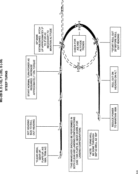
(1) Steep bank turns—Each steep turn must involve a bank angle of 50 degrees with a heading change of at least 180 degrees but no more than 360 degrees.
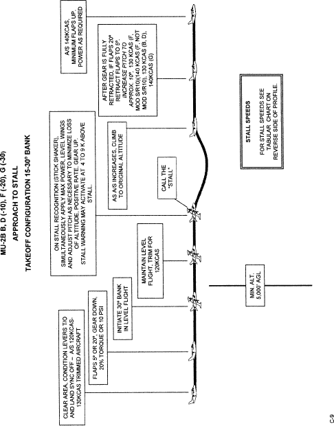
(2) Approaches to stalls—Must be performed in each of the following configurations; takeoff, clean, and landing. One approach to a stall must be performed in either the takeoff, clean, or landing configuration while in a turn with a bank angle between 15 degrees and 30 degrees.
(3) Accelerated stalls—must be done in the flaps 20 and flaps 0 configurations.
(4) Recovery procedures must be initiated at the first indication of a stall.
Normal and Abnormal Procedures and Operations
(1) Runway trim.
(2) Normal and abnormal operations of the following systems:
(a) Pressurization.
(b) Pneumatic.
(c) Air conditioning.
(d) Fuel.
(e) Electrical.
(f) Flight control.
(g) Anti-icing and de-icing.
(h) Autopilot.
(i) Stall warning devices, as applicable.
(j) Airborne radar and weather detection devices.
(k) Other systems, devices or aids available.
(l) Electrical, flight control and flight instrument system malfunction or failure.
(m) Landing gear and flap system malfunction or failure.
(n) Failure of navigation or communications equipment.
Flight Emergency Procedures
(1) Powerplant failure.
(2) Powerplant, cabin, flight deck, wing and electrical fires.
(3) Smoke control.
(4) Fuel jettisoning, as applicable.
(5) Any other emergency procedures outlined in the appropriate AFM or FAA-accepted checklist.
Instrument Procedures
(1) Area departure.
(2) Use of navigation systems including adherence to assigned course and/or radial.
(3) Holding procedures.
(4) Aircraft approach category airspeeds.
(5) Approach procedures: Each instrument approach must be performed according to all procedures and limitations approved for that facility. An instrument approach procedure begins when the airplane is over the initial approach fix for the approach procedure being used and ends when the airplane touches down on the runway or when transition to missed approach configuration is completed.
(a) ILS, ILS/DME, approach.
(i) A manually controlled ILS with a powerplant inoperative; occurring before initiating the final approach course and continuing to full stop or through the missed approach procedure.
(ii) A manually controlled ILS utilizing raw data to 200 feet or decision height (DH).
(iii) An ILS with the autopilot coupled.
(b) Non-precision approaches.
(i) NDB, NDB/DME approach, straight in or circle.
(ii) VOR, VOR/DME, straight in or circle.
(iii) LOC, LOC/DME, LOC backcourse.
(iv) GPS approach (If the aircraft/FTD/flight simulator has a GPS installed, the applicant must demonstrate GPS approach proficiency.)
(v) ASR approach.
(c) Missed approach procedure: One missed approach procedure must be a complete approved missed approach procedure as published or as assigned by ATC.
(i) From a precision approach.
(ii) From a non-precision approach.
(iii) With a simulated powerplant failure.
(d) Circling approach.
(i) The circling approach must be made to the authorized MDA and followed by a change in heading and the necessary maneuvering (by visual reference) to maintain a flight path that permits a normal landing on the runway.
(ii) The circling approach must be performed without excessive maneuvering and without exceeding the normal operating limits of the airplane and the angle of bank must not exceed 30°.
Landings and Approaches to Landings
(1) Airport orientation.
(2) Normal landings with stabilized approach.
(3) Crosswind landings.
(4) From a precision instrument approach.
(5) From a precision instrument approach with a powerplant inoperative.
(6) From a non-precision instrument approach.
(7) From a non-precision instrument approach with a powerplant inoperative.
(8) From a circling approach or VFR traffic pattern.
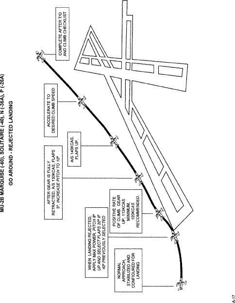
(9) Go Around/Rejected landings—a normal missed approach procedure or a visual go-around after the landing is rejected. The landing should be rejected at approximately 50 feet and approximately over the runway threshold.
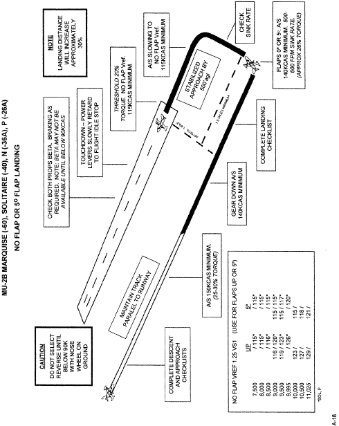
(10) Zero flap landing.
(a) Runway requirements.
(b) Airspeeds.

Appendix D to SFAR 108—MU–2B Maneuver Profiles
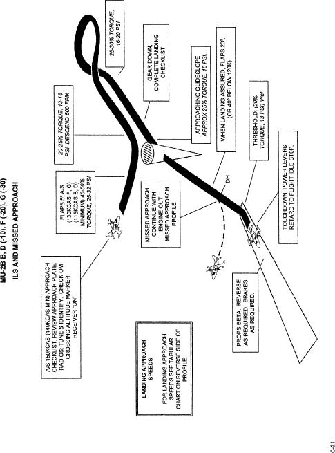
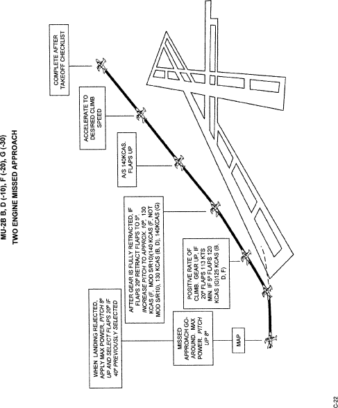
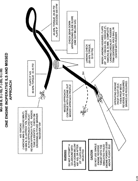
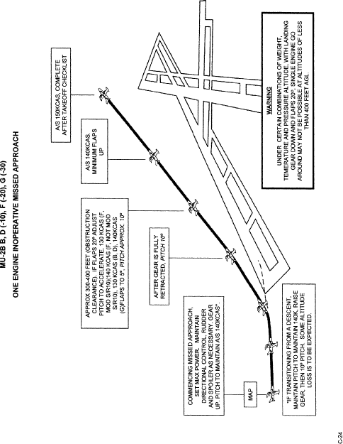
(A) The Maneuver Profiles are provided to develop pilot proficiency with the procedures and techniques contained within this MU–2B Flight Training Program.
(B) Though constructed for use in the airplane they may also be used in the Flight Training Device (FTD). When an FTD is used, a maneuver may be performed at lower altitudes or carried to its completion. When training is conducted in the MU–2B airplane, all maneuvers must be performed in a manner sufficient to evaluate the performance of the student while never jeopardizing the safety of the flight.
(C) The maneuvers profiles are broken down into three sections by similar aircraft model groups. The three sections of this program are:
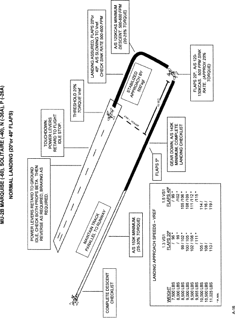
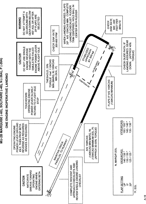
(1) Marquise (−60), Solitaire (–40), N (–36A), P (–26A)—Figures A–1 through A–28
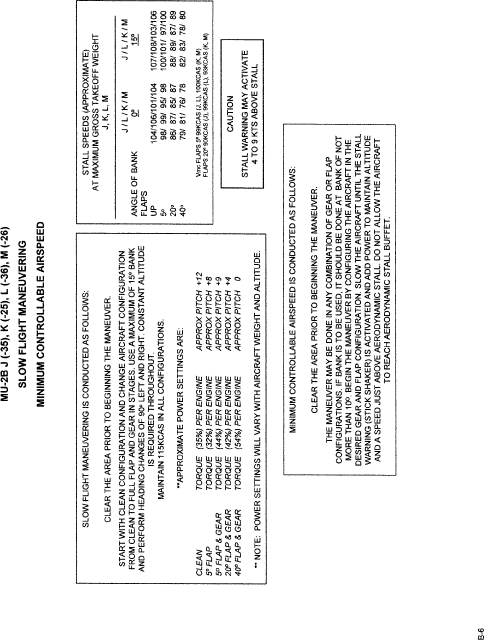
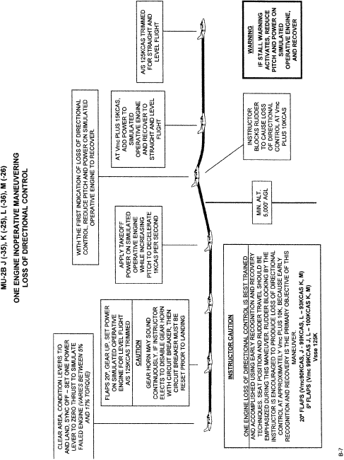
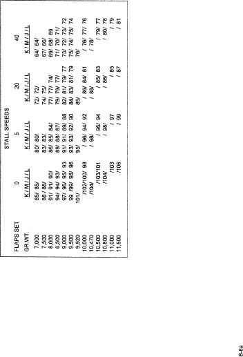
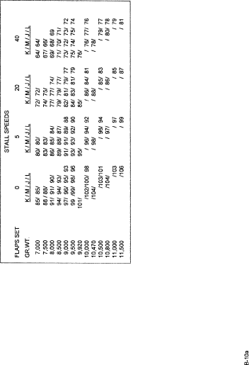
(2) J (–35), K (–25), L (–;36), M (–26)—Figures B–1 through B–28
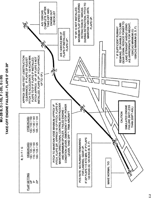
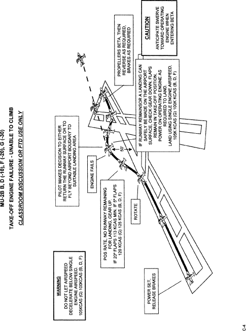
(3) B, D (–10), F (–20), G (–30)—Figures C–1 through C–28
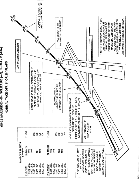
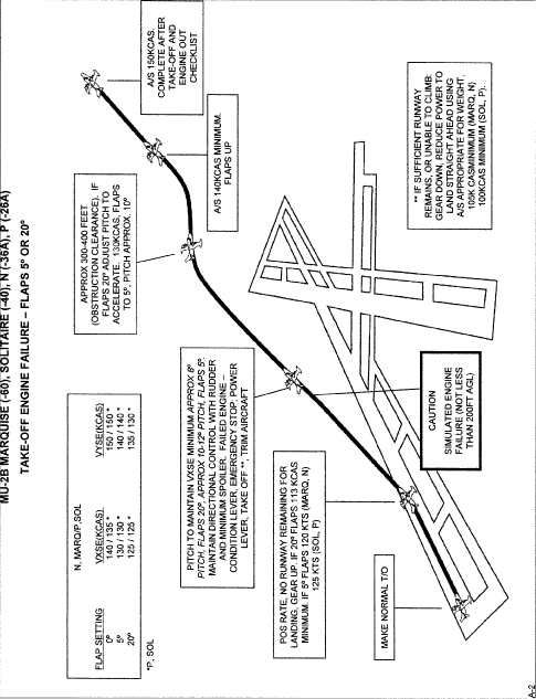
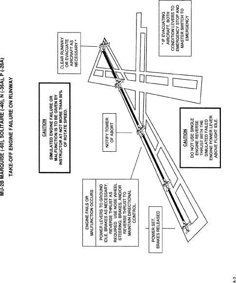
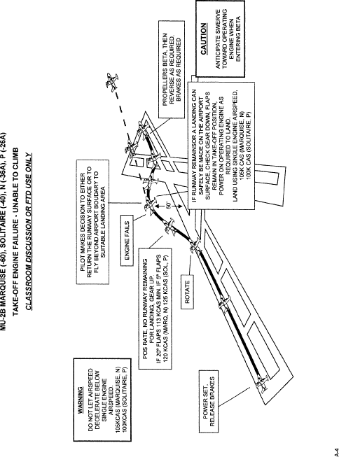
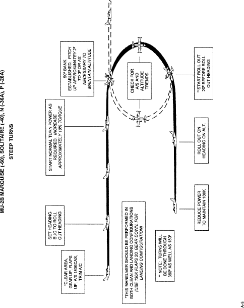
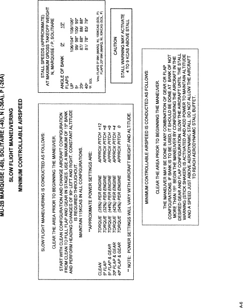
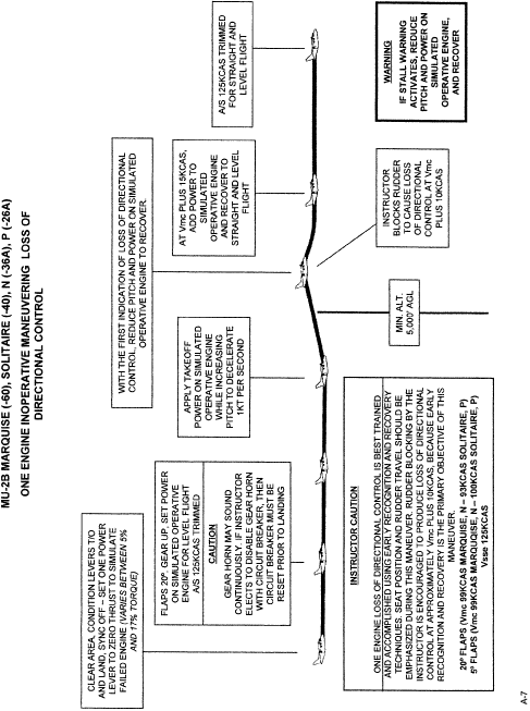

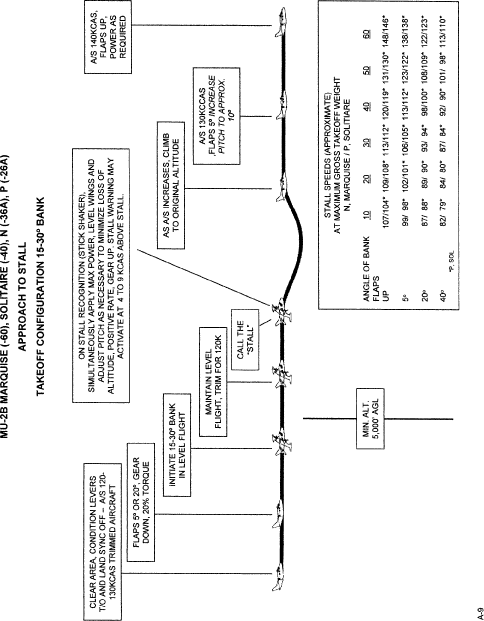

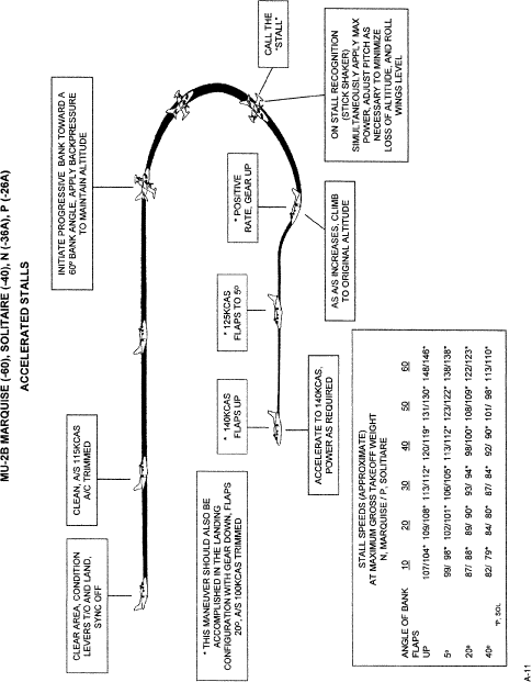

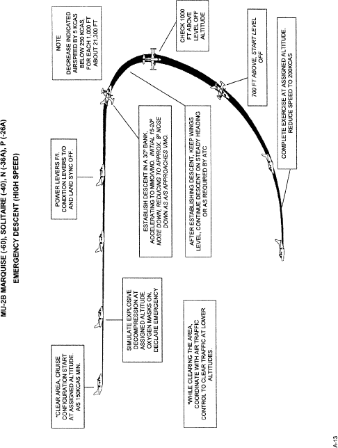
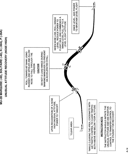
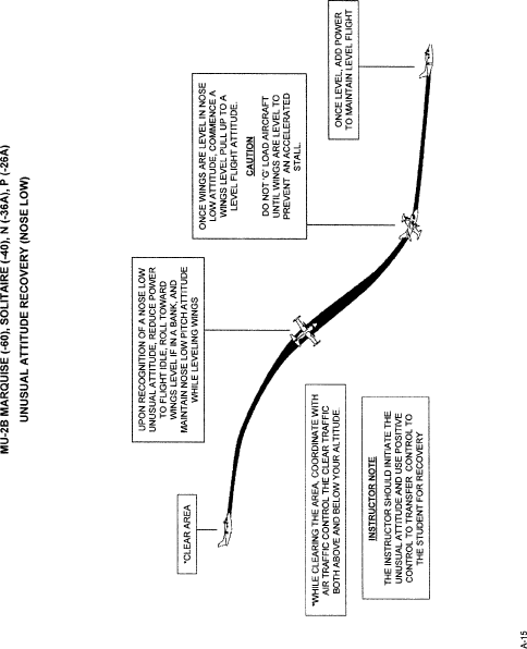


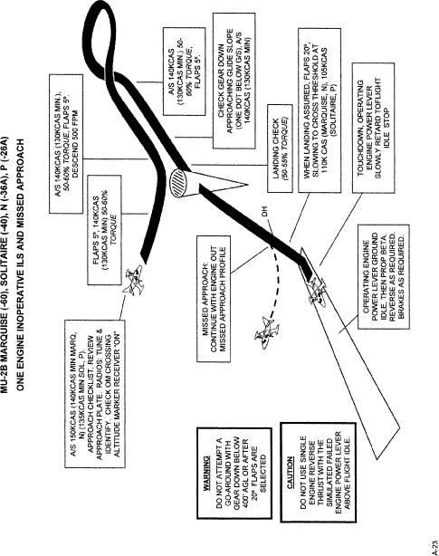
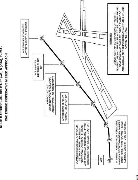
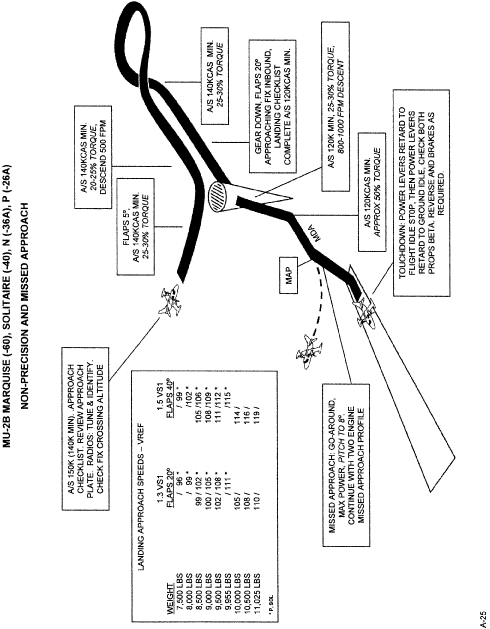
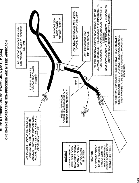
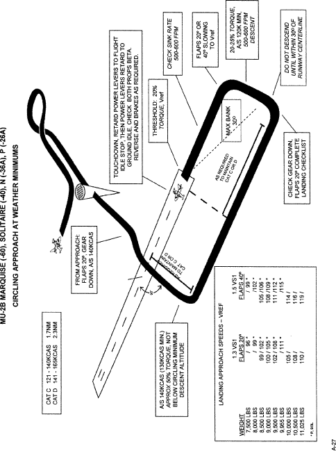
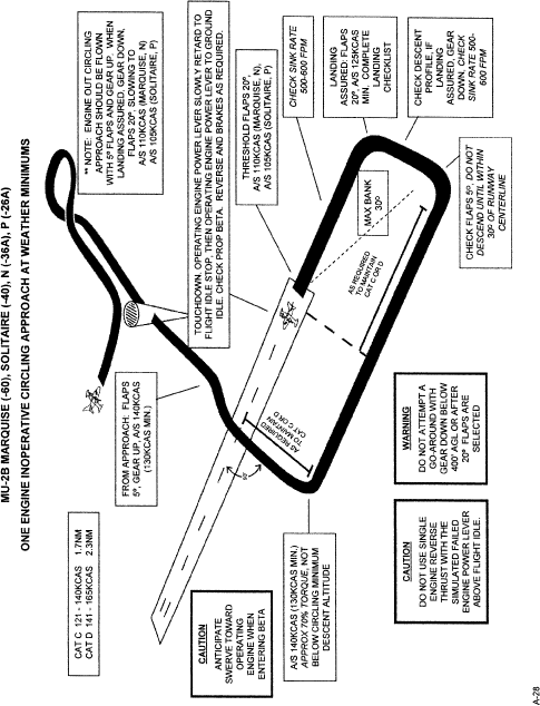
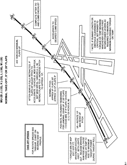


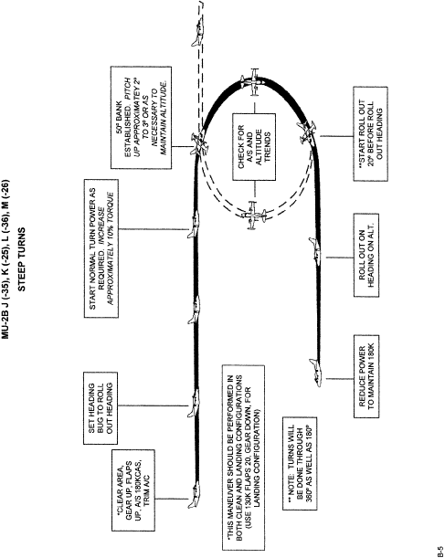





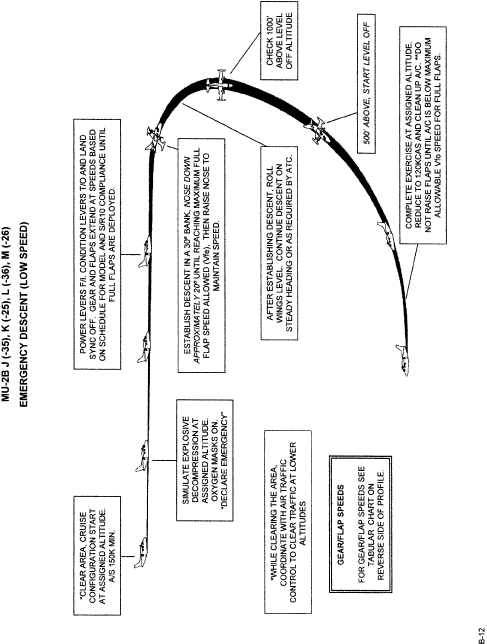
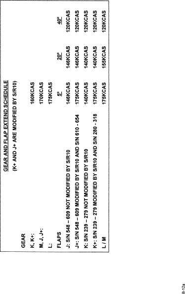
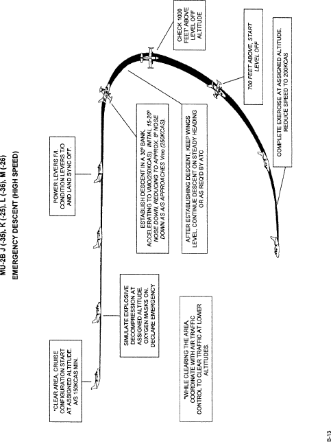
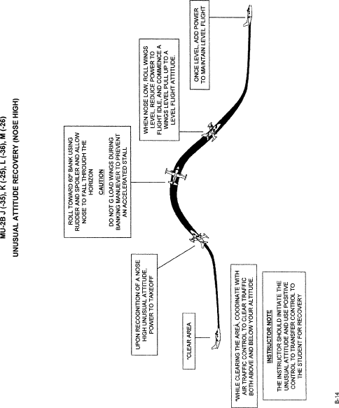


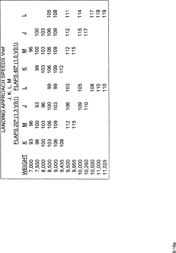

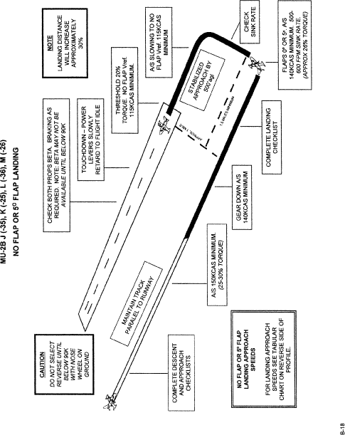
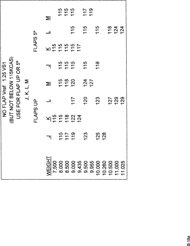

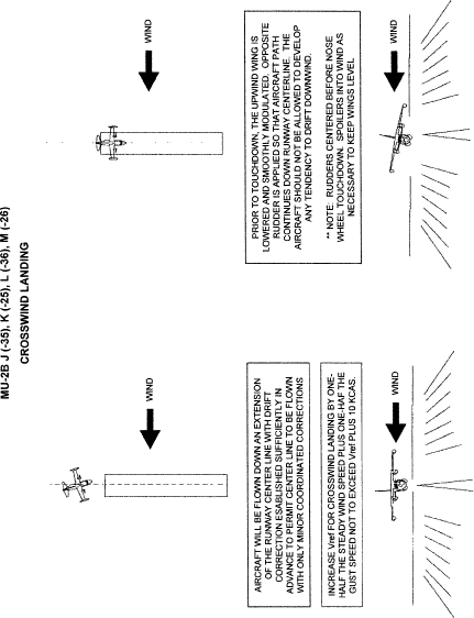
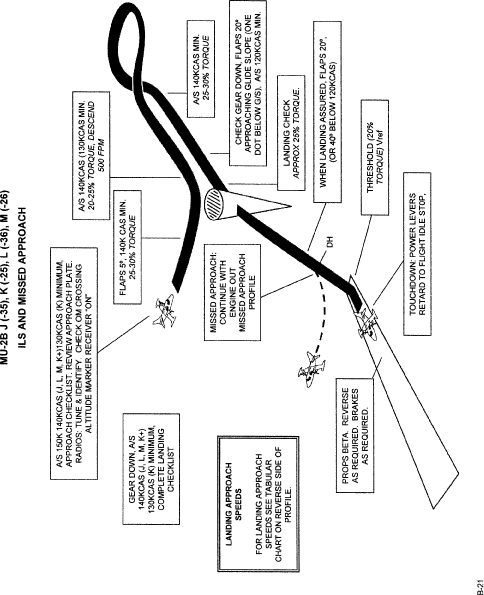
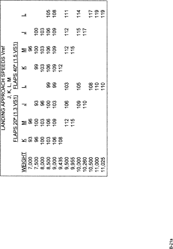
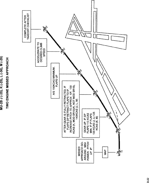
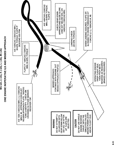

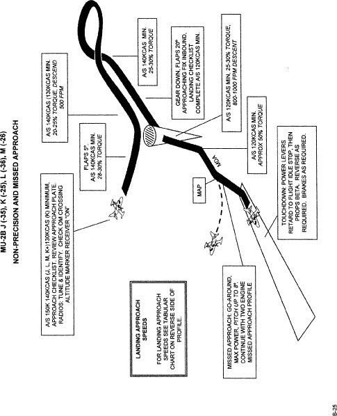
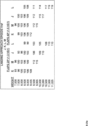
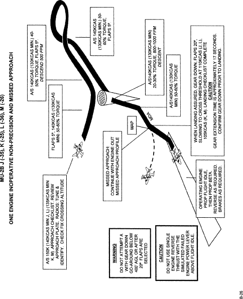
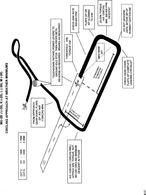

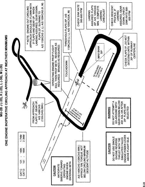





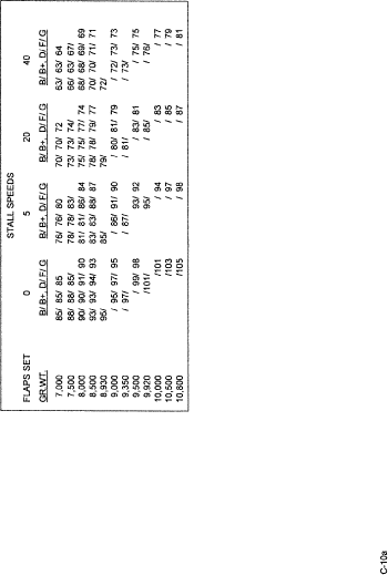

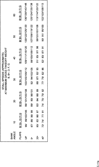

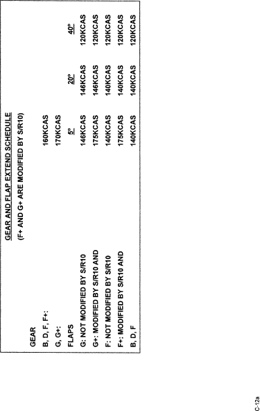


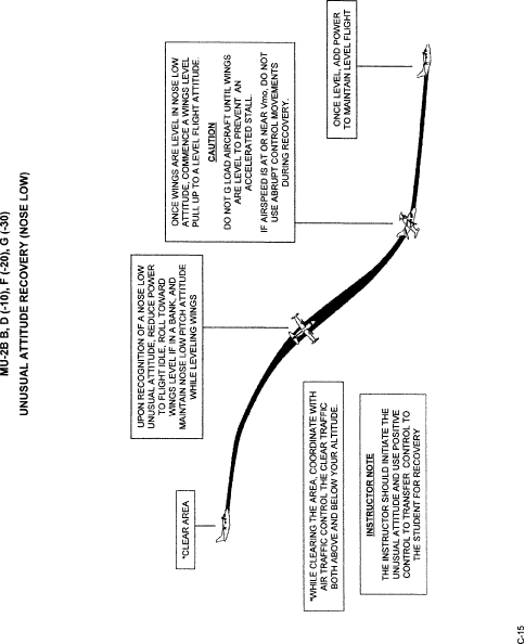
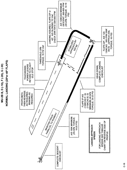
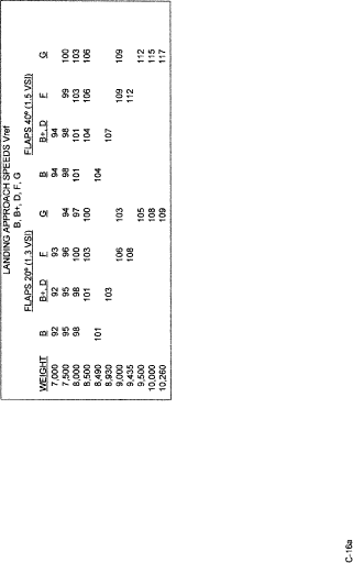
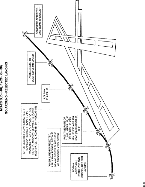
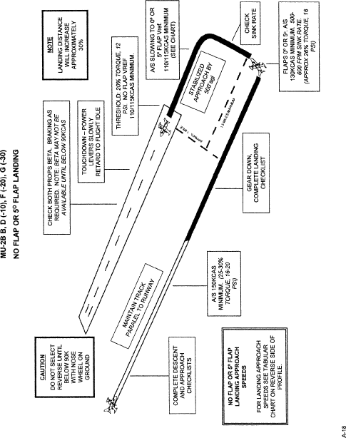
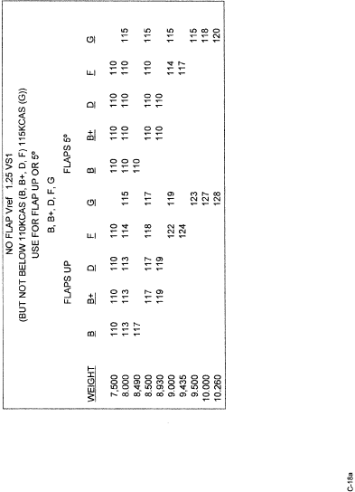
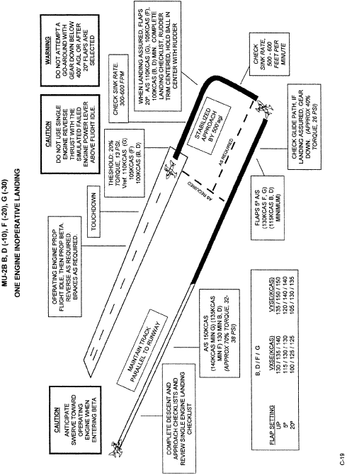
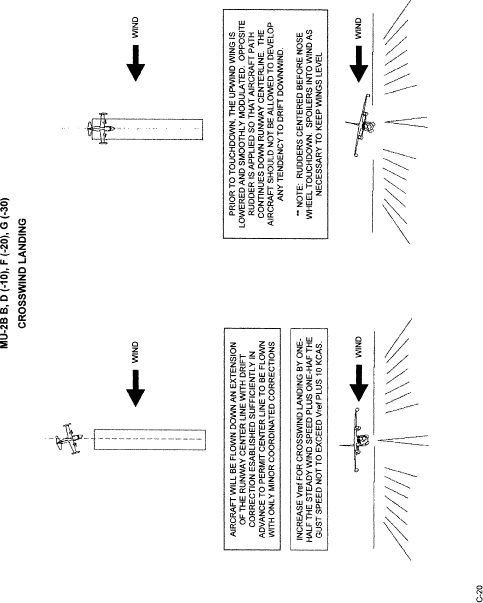

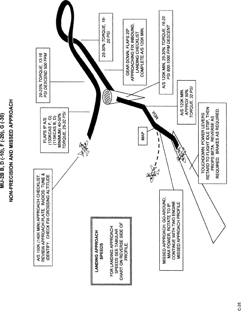

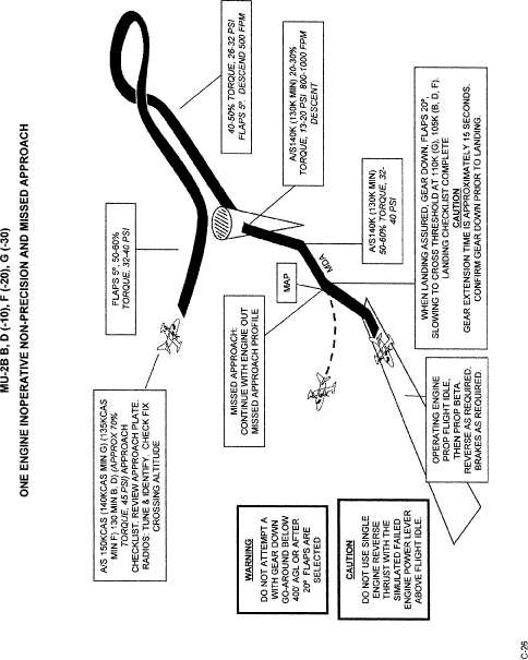
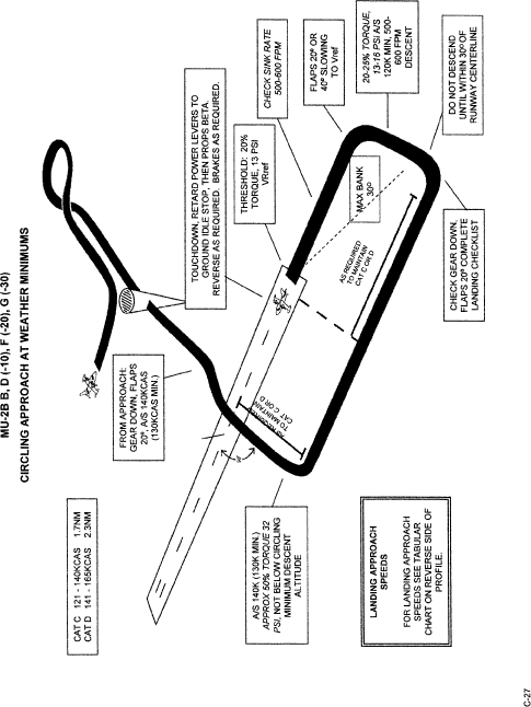
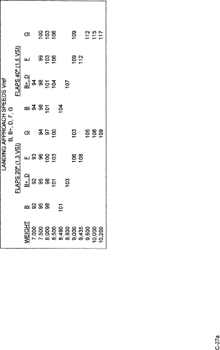
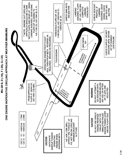
(D) Each MU–2B profile in its respective section follows the outline below.
(1) Normal Takeoff (5- and 20-degrees flaps).
(2) Takeoff Engine Failure (5- and 20-degrees flaps).
(3) Takeoff Engine Failure on Runway or Rejected Takeoff.
(4) Takeoff Engine Failure after Liftoff—Unable to Climb (Classroom or FTD only).
(5) Steep Turns.
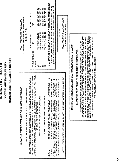
(6) Slow Flight Maneuvers.
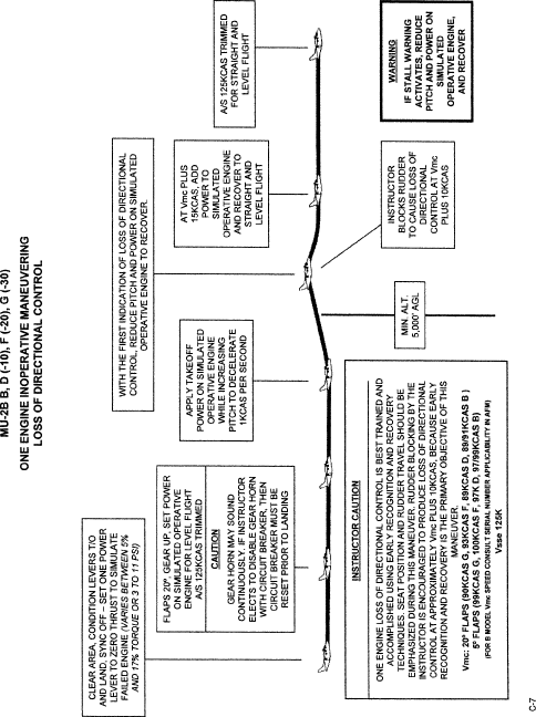
(7) One Engine Inoperative Maneuvering/Loss of Directional Control.
(8) Approach to Stall (clean configuration/wings level).
(9) Approach to Stall (takeoff configuration/15- to 30-degrees bank).
(10) Approach to Stall (landing configuration/gear down/40-degrees flaps).
(11) Accelerated Stall (no flaps).
(12) Emergency Descent (low speed).
(13) Emergency Descent (high speed).
(14) Unusual Altitude Recovery (nose high).
(15) Unusual Altitude Recovery (nose low).
(16) Normal Landing (20- and 40-degrees flaps).
(17) Go Around/Rejected Landing.
(18) No Flap or 5-degrees flaps Landing.
(19) One Engine Inoperative Landing (5- and 20-degrees flaps).
(20) Crosswind Landing.
(21) ILS and Missed Approach.
(22) Two Engine Missed Approach.
(23) One Engine Inoperative ILS and Missed Approach.
(24) One Engine Inoperative Missed Approach.
(25) Non-Precision and Missed Approach.
(26) One Engine Inoperative Non-Precision and Missed Approach.
(27) Circling Approach at Weather Minimums.
(28) One Engine Inoperative Circling Approach at Weather Minimums.
Engine Performance
(A) The following should be considered in reference to power settings and airspeeds:
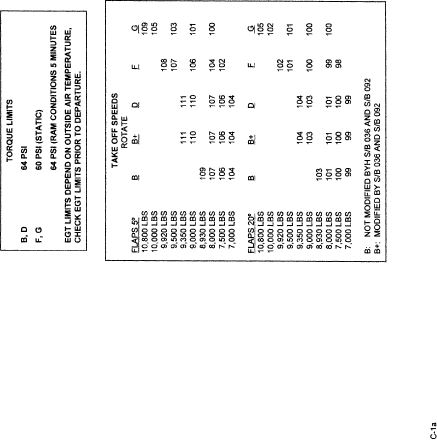
(1) Power settings shown in italics are provided as guidance only during training and are not referenced in the AFM. Power setting guidance is provided to show the approximate power setting that will produce the desired airspeed or flight condition. Actual power settings may be different from those stated and should be noted by the instructor and student for reference during other maneuvers. Power settings in the profiles are stated in torque or PSI and will vary with aircraft model, engine model, weight, and density altitude. Power settings are based on standard atmospheric conditions.
(2) Some pilots prefer to set power initially using fuel flow, because the fuel flow system is not field adjustable. Fuel flow settings refer to engine operations only. If fuel flow is used to set power for takeoff, check torque and temperature after setting fuel flow and adjust torque or temperature, whichever is limiting, for maximum takeoff power prior to liftoff.
(3) Improperly adjusted torque or improperly calibrated temperatures are a safety of flight issue and must be checked and corrected prior to conducting flight training.
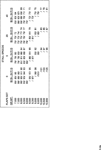
(4) The pilot should refer to the performance section of the airplane flight manual to determine actual speeds required for his/her particular model and specific weight for any given operation.
In Flight Maneuvering
(A) Maneuvers conducted at altitude such as stalls and steep turns must always be preceded by clearing turns and at least one crew member must continually clear the flying area during the maneuver. The instructor must emphasize the importance of clearing the area, even if the maneuvers are being done in an FTD or simulator. This will create the habit pattern in the pilot to clear the area before practicing maneuvers.
(B) During stalling maneuvers and upon recognition of the indication of a stall, the pilot must call the “stall” to the instructor and then proceed with the recovery. In addition, during training, the pilot must announce the completion of the stall recovery maneuver. Instructors must exercise caution when conducting stall maneuvers and be prepared to take the controls if the safe outcome of the maneuver is in doubt.
(C) During accelerated stall maneuvers, it is important that the instructor pay close attention to the position of the ball throughout the maneuver and recovery so as to maintain coordinated flight. Stall recognition and recovery is the completion criteria, and it is not necessary to continue the stall beyond the stick shaker to aerodynamic buffet.
(D) When demonstrating a loss of directional control with one engine inoperative, the engine failure must only be simulated. During the slowing of the aircraft to demonstrate loss of directional control, the instructor should use the rudder block method to allow the student to experience the loss of directional control associated with VMC, at a speed of approximately 10 knots above actual VMC.
Note: To accurately simulate single engine operations, zero thrust must be established. The zero thrust torque setting will vary greatly from model to model. It is important to establish to zero thrust torque setting for your aircraft. This requires that the aircraft be flown on one engine to establish the zero thrust setting. This is accomplished by establishing single engine flight with one propeller feathered and noting the performance with the operating engine at maximum torque or temperature. It is suggested that two airspeeds be established for zero thrust power settings. They are 120 kts, flaps 20, gear up for takeoff and 140 knots, flaps 5, gear up for in-flight and approach maneuvering. Once performance has been established and recorded for each airspeed, restart the other engine and find the torque setting that duplicates the performance (climb or descent rate, airspeed) as was recorded with that propeller feathered. This torque setting will be zero thrust for the simulated inoperative engine. The student/pilot should note that the performance experienced with one engine operating at flight idle, may produce greater performance than if the engine were stopped and the propeller feathered.
Pre-maneuver briefings for any maneuver that requires either an actual engine shutdown or a simulated engine failure must be undertaken when using an aircraft. In the case of an actual engine shutdown, a minimum altitude of 3,000 ft above ground level (agl) must be used and done in a position where a safe landing can be made at an airport in the event of difficulty.
Takeoff and Landing
(A) When using the profiles to establish the procedure for configuring the aircraft for takeoff or landing, it is important to understand that each task for the procedure, as noted on the procedure diagram, establishes the point at which each task should have been completed and not the exact point at which the task should be accomplished unless otherwise stated in the task box. Numbers which represent performance such as descent rates or other maneuvering information that is not contained in the aircraft flight manual are shown in italics.
(B) In all takeoff profiles the prompt for the gear to be retracted is “No Runway Remaining, Gear Up”. This should set the decision point for making a landback after an engine failure and should normally be reached at altitudes of less than 100 ft AGL. It is impractical to attempt a landback from above 100 ft AGL, because it can require distances up to 10,000 ft from the beginning of the takeoff run to bring the aircraft to a stop. But, even on very long runways, landback will not be necessary above 100 ft AGL and above Vyse for the flap configurations, if the single engine climb capability found in the POM charts, with the gear up, is positive (250 fpm or better) and obstacles clearance is not an issue.
(C) The manufacturers FAA-accepted checklists and checklist in Appendix C to this SFAR No. 108 describe a procedure for the discontinuance of flight following an engine failure after takeoff and the realization that the aircraft cannot climb. The corresponding flight profile in this training program is “Takeoff Engine Failure, Unable to Climb”. This maneuver must not be attempted in the aircraft, but must be the subject of a classroom discussion or be demonstrated in the FTD.
(D) The focus of all landing procedures, whether two engine or engine out, is on a stabilized approach from an altitude of 500 feet. This will not be possible for all approach procedure maneuvering, especially during non-precision or circle to land approaches. Approach procedures for these two approaches should be stabilized from the point at which the pilot leaves the Minimum Descent Altitude for the landing.
(E) When performing one engine inoperative approaches, landings or missed approaches, the instructor must be prepared to add power to the simulated failed engine at the first sign of deteriorating airspeed or other situation that indicates the student's inability to correctly perform the maneuver.
(F) While maneuvering in the pattern or during instrument approach procedures with one engine inoperative, a 30° bank angle must not be exceeded. This will become especially important when executing non-precision and circle to land approaches.
Emergency and Abnormal Procedures
(A) During training, either in the FTD or in the aircraft, the performance of emergency and abnormal procedures is critical to the completion of the training program. All emergency and abnormal procedures should be simulated when training in the MU–2B airplane.
(B) When presenting emergency scenarios to the student, the instructor must not introduce multiple emergencies concurrently.
Scenario Based Training (SBT)
SBT flight training creates an environment of realism. The SBT programs utilize a highly structured flight operation scenario to simulate the overall flight environment. The pilot is required to plan a routine, point-to-point flight and initiate the flight. During the conduct of the flight, “reality-based” abnormal or emergency events are introduced without warning. Because the pilot is constantly operating in the world of unknowns, this type of training also builds in the “startle factor”, and just as in the real-world, the consequences of the pilot's actions (decisions, judgment, airmanship, tactile skills, etc.) will continue to escalate and affect the outcome of the planned flight. Although flying skills are an integral part of this type of training, SBT enables the pilot to gain experience in dealing with unexpected events and more importantly further enhances the development of good judgment and decisionmaking.
[Doc. No. FAA–2006–24981, 73 FR 7051, Feb. 6, 2008]
| File Type | application/msword |
| File Title | Special Federal Aviation Regulation No |
| Author | Taylor CTR Dahl |
| Last Modified By | Taylor CTR Dahl |
| File Modified | 2011-01-24 |
| File Created | 2011-01-24 |
© 2026 OMB.report | Privacy Policy