HPMS Manual Ch5
chap5.doc
Highway Performance Monitoring System (HPMS)
HPMS Manual Ch5
OMB: 2125-0028
Chapter V HPMS Field Manual
December 2000
Chapter V
Linear Referencing System Requirements
In the past, HPMS data has been analyzed and viewed as tables, charts, and graphs. Furthermore, any analysis of HPMS data could only include data fields contained within the HPMS with little opportunity to use information outside it. With the advent of Geographic Information Systems (GIS), a new spatial dimension is now being introduced into HPMS analysis.
What is GIS? Within the context of this chapter, it is sufficient to say it is a way to view and analyze data spatially using specialized software. What this means is that previously discrete databases can now be related together and examined; a relationship that exists through the spatial coordinates these data share. While there are a variety of methods used to locate objects in the real world, the most commonly used among State Departments of Transportation (DOTs) are Linear Referencing Systems (LRS). This chapter contains the requirements for reporting the State’s LRS data. The guidelines presented will allow the State to submit its LRS information in a format that will allow it to be incorporated into the FHWA’s GIS.
The GIS will advance HPMS state-of-the-art and will enable FHWA, the States, and others to analyze HPMS data for rural arterials, urban principal arterials, and other NHS roadways within a spatial context. The ability to integrate data through GIS will result in enhanced analysis and presentation of the HPMS data State and Nation wide. Introducing this spatial component facilitates greater versatility of the HPMS in its application and integration with other databases, and enables the HPMS to meet the increasing demands placed on it as a transportation analytical and management tool. The HPMS GIS is an important step to increase the effectiveness of HPMS as an information system. The LRS information submitted in accordance to Chapter V is in addition to the LRS information reported in Chapter IV.
The LRS reported in this chapter will be integrated into the National Highway Planning Network (NHPN). The NHPN is the database that contains the geographic or spatial locations of the Nation's principal highways. The NHPN, initially developed in a separate mid-1980’s effort sponsored by FHWA, is a digital database representing the National Highway System and the remaining rural arterials and urban principal arterials. The NHPN was developed based on 1:100,000 Digital Line Graphs (DLGs) from the U.S. Geological Survey and augmented by State-supplied information describing roads and streets not represented in the DLGs. In this context, the NHPN represents highway geometry, and the HPMS is its attributes. The two databases are related to each other via LRS information. The LRS, in effect, gives each data base addresses that can be identified in the real world. Through this tie, any location in the NHPN should have a corresponding HPMS record. The two data bases are being brought together through a process called dynamic segmentation, which in many ways resembles a simple database relate. To perform a relate, common fields must exists in all identified databases. In this case, the common fields used to link HPMS to the NHPN are:
County FIPS
Inventory Route Number
Inventory Subroute Number
Kilometerpoint/Milepoint (KMPT/MPT)
The combination of these data will identify a unique location on the State’s highway system. Anything less than this could give ambiguous results.
The county, inventory route, and inventory subroute fields are used to identify a particular portion of a route. The beginning and ending KMPT/MPT fields are used to find a specific location along a route. The general model for an LRS is that one end of the route is identified as its point of origin. It then accumulates measured distance along its course, in KMPTs/MPTs, until it reaches the end of the route. Typically, States modify this concept to meet their own particular needs. Regardless of how the State accomplishes this, all methods of identifying roadway features can be related back to the general model described above. The instructions in this chapter were written to accommodate the State’s existing LRS in order to ensure long-range State support of the LRS and a continuing tie between HPMS and State databases.
Because of the detail involved, all figures in this chapter contain English units. Metric units may be substituted.
The NHPN with LRS attached (either in its entirety or by State or portion thereof) is available to the States and others for use in their GIS activities. The NHPN serves as a national framework for information exchange and will be provided to the U.S. Geological Survey, the Bureau of Census, the Intelligent Transportation System (ITS) community, and the Bureau of Transportation Statistics (BTS) to represent the higher order highways.
GENERAL LRS RULES
One of the biggest challenges faced by the FHWA is converting the 52 different State LRSs into one consistent national LRS. In order to accomplish this efficiently, some rules of standardization must be followed. These rules focus on fundamental components of the LRS by addressing three general areas.
Defining inventory routes.
The placement of nodes. Some SHAs do not use nodes in their LRS; however, the FHWA requires the use of nodes for the purpose of LRS accuracy. These nodes do not require the State to change its own internal LRS but have been defined to allow them to be easily added without affecting the former.
Incorporating LRS discontinuities.
The LRS used is a conventional KMPT/MPT. The KMPT/MPT represents the distance in kilometers/miles along the route from a reference point. The reference point can be a State boundary, county boundary, or the beginning point of a route. This distance may be modified by physical route breaks and KMPT/MPT equations that compensate for gaps or excess KMPT/MPT brought on by realignments or recalibration. The following general rules apply:
Base Network:
All NHS plus remaining rural and urban principal arterial and rural minor arterial routes must have an inventory route number. Existing State inventory routes should be used to maximize the relationship between the State’s own road inventory and HPMS databases. These routes can consist of both existing and planned unbuilt facilities (see Item 20 in Chapter IV).
General LRS Definition:
An LRS will be defined for each of the inventory routes identified above.
Only one LRS is to be reported for each inventory route. Independently aligned roadways (divided highways) are treated as one highway with one KMPT/MPT system.
Two or more inventory routes may not be assigned to a given highway link (a stretch of roadway between any two corresponding nodes—see Node Location Criteria below). For HPMS reporting purposes, one inventory route must be chosen to represent the link and the remaining inventory route(s) must be ended and restarted where it diverges from the chosen inventory route.
Ramps and collectors/distributors are considered to be part of the mainline system and do not have separate LRSs. Frontage roads belong to functional systems of their own and are to be treated as separate roadways.
Node Location Criteria:
A single node must be established at the following points:
Beginning of an inventory route
Where the inventory route crosses another inventory route(s)
Where the inventory route crosses a county line
Where the inventory route encounters an equation
Where the inventory route is temporarily suspended or incurs other types of physical breaks
Where the inventory route ends
Defining Unique Locations:
A unique location within a State for the HPMS LRS is defined by the combination of county, inventory route, inventory subroute, and KMPT/MPT.
Under certain conditions, duplicate KMPTs/MPTs can occur along a route in a state's linear referencing system. These conditions can occur when the route encounters certain types of equations, route breaks, or county lines. Duplicate KMPTs/MPTs are not allowed on a given inventory route within a county. Inventory subroutes must be used to independently identify highway links with duplicate KMPTs/MPTs.
F
igure
V-1. Duplicate Milepoint Equation
Equations: Locations on a route where discontinuities in KMPTs/MPTs occur (usually caused by construction) are remedied in some State systems through the establishment of an equation. Some equations will create two lengths of roadway with duplicate ranges of KMPTs/MPTs; i.e., the BACK KMPT/MPT is larger than the AHEAD KMPT/MPT. In such instances, a subroute number must be used to distinguish between duplicate KMPTs/MPTs.
For example, on inventory Route 101, an equation of BACK 20.00 = AHEAD 18.50 creates two 1.50 mile lengths of road with the range of milepoints from 18.50 to 20.00. The route starts at 0.00 milepoint and goes to BACK 20.00 where the mileage is adjusted to AHEAD 18.50, and goes to the end at milepoint 40.00. This route needs to be divided into two subroutes to distinguish between the duplicate milepoints. Subroute number 00 starts at 0.00 milepoint and goes to BACK 20.00. Subroute number 01 starts at AHEAD 18.50 milepoint and goes forward to milepoint 40.00 as illustrated in Figure V-1. The subroute number is continued until either another occurrence of duplicate KMPTs/MPTs (another equation, a route break, or a county boundary) is encountered or the end of the route is reached. For example, if another equation (like the one mentioned above) is encountered, then the subroute number is incremented to 02, etc.
C
Figure
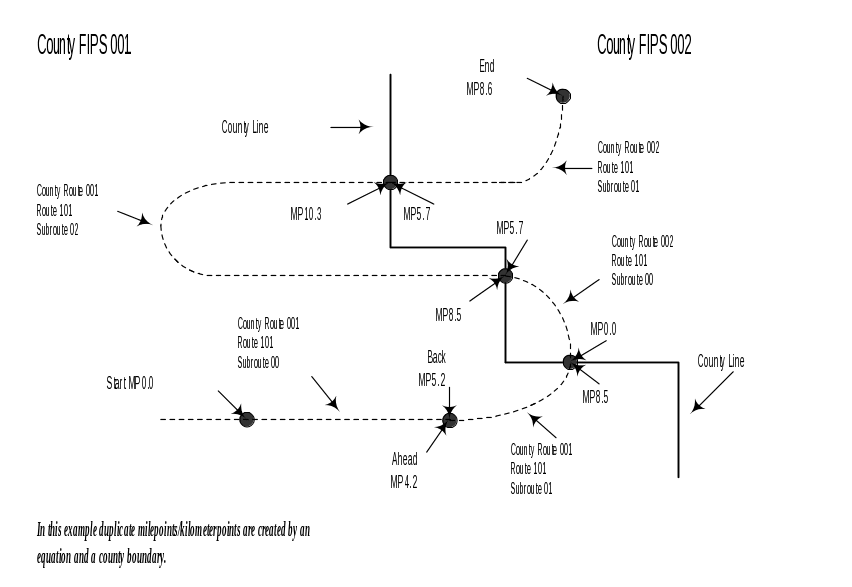
V-2. Re-Entering a County; Equation Created

ounty
Reentries and Route Breaks: When a route
reenters a county or a route break occurs (and the intervening
mileage is not counted) and duplicate KMPTs/MPTs occur, inventory
subroutes must be used to properly identify highway links. For
example, in Figure V-2, inventory Route 101 reenters counties 001 and
002 with the entry KMPTs/MPTs equal to the exit milepoints, requiring
the subroute numbers to be incremented to maintain uniqueness within
the counties.
In Figure V-3, the length of discontinuity in inventory Route 101 is ignored, and the inventory subroute must be incremented to recognize the duplicate KMPTs/MPTs.
F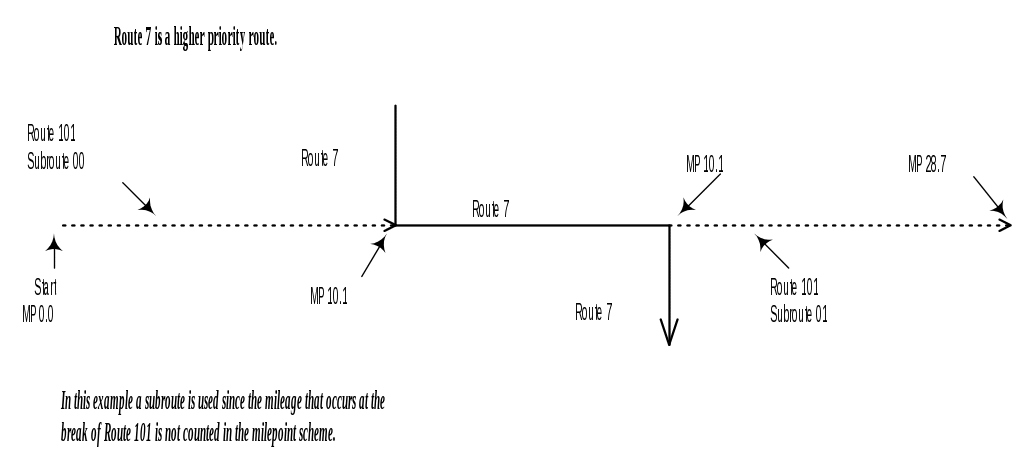
igure
V-3. Route Stops and Restarts at a Different Location; Milepoint
Stays the Same
Subroutes:
An inventory route's subroute numbers must not be duplicated within any one county.
Inventory subroutes along a route do not have to be in order.
Inventory subroutes need not be used in cases where gaps in kilometers/milepoints occur on an inventory route. In many cases, duplicate KMPTs/MPTs do not exist on inventory routes. In these instances, KMPTs/MPTs are either continuous or gaps occur where KMPTs/MPTs are skipped. These situations do not require the use of inventory subroutes to uniquely identify links (i.e., the subroute is “00” or remains at the last established value).
Equations that are used to compensate for a gap in the KMPT/MPT system are those in which the BACK KMPT/MPT is smaller than the AHEAD KMPT/MPT. For example, an equation of BACK 12.15 = AHEAD 15.55 creates a 3.40-mile gap in the milepoint system (Figure V-4).
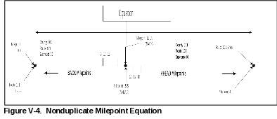
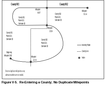
Likewise, an inventory route can be stopped and restarted at another location without duplicating KMPTs /MPTs (Figures V-5 and V-6). In the above instances, duplicate KMPTs/ MPTs are not created since the intervening mileage is kept. No changes in inventory subroutes are required.
If no duplicate KMPT/ MPT condition exists within the county, the combination of county, inventory route, and KMPT/MPT will identify a unique location.
F
igure
V-6. Route that Stops and Restarts at Different Locations; Milepoint
Increases
Effects of LRS on HPMS Sections:
HPMS sections must be adjusted (or divided) where inventory routes or subroutes change along the length of that section. The division of inventory routes into inventory subroutes, where duplicate KMPTs/MPTs occur, could have a direct impact on the physical length of HPMS universe and sample sections. The subroute field effectively creates a new route any time the subroute number changes.
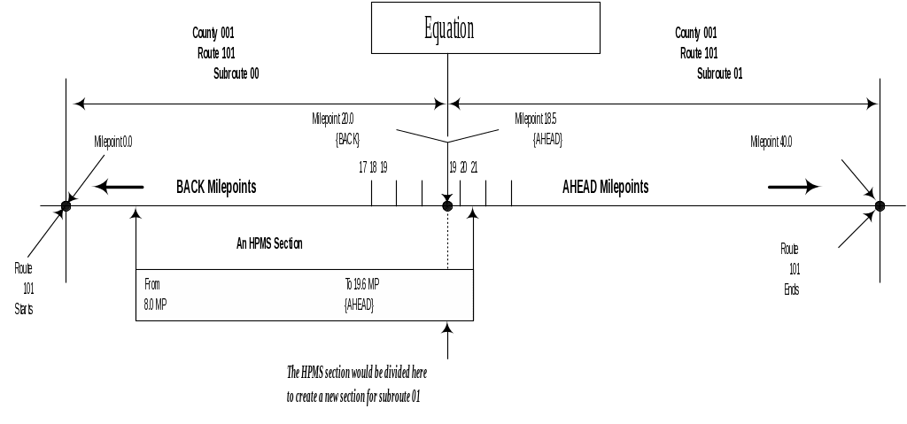
Figure V-7 shows an HPMS section starting at milepoint 8.0 and extending to milepoint BACK 19.6 - not AHEAD 19.6. In this case, no change to the HPMS section is necessary since the section occurs entirely within county 001, Route 101, Subroute 00. Figure V-8 illustrates the same route conditions with the exception that the HPMS section starts at milepoint 8.0 and extends to milepoint AHEAD 19.6 - not BACK 19.6. In this case, the HPMS section must be adjusted (or divided) at that equation point to accommodate the duplicate KMPTs/MPTs. Two sections must be created: milepoint 8.0 to the equation
and then from the equation to milepoint AHEAD 19.6.
In contrast, where an HPMS section crosses a nonduplicating equation point, the section need not be adjusted (see Figure V-9).
Because of inventory route design, an HPMS section may have more than one inventory route traversing it. Where this occurs, the HPMS section must be divided to reflect the beginning and ending of the inventory routes. Figure V-10 shows an HPMS section extending across two inventory routes: 101 and 7. In this case, the HPMS section must be divided into three sections at the points where the inventory route changes. Since HPMS sections should already begin/end at county lines, no modification to the sections is required where subroutes are created at county lines.
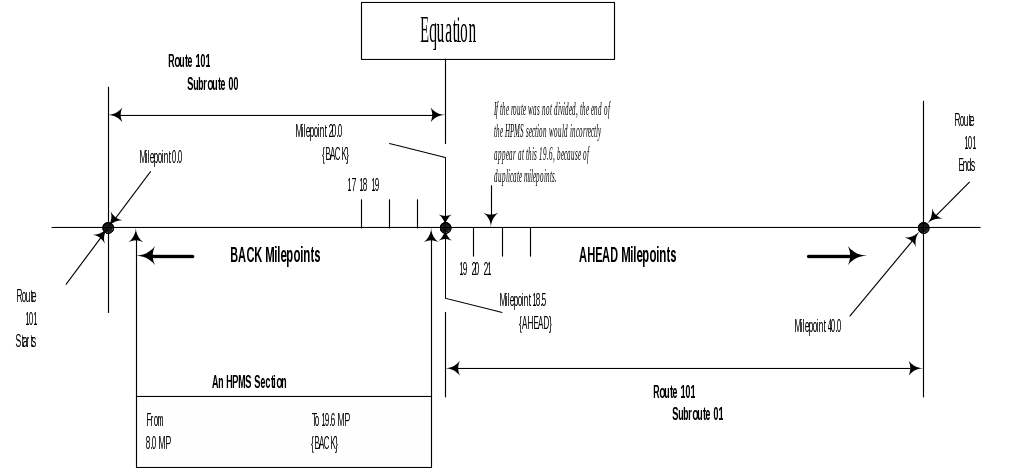

Figure V-7. HPMS Section Near a Duplicate Milepoint Equation
Figure V-8. HPMS Section Crossing a Duplicate Milepoint Equation
F
igure
V-9. HPMS Section Crossing a Nonduplicate Milepoint Equation
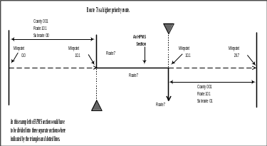
Figure V-10. An HPMS Section that Runs through Overlapping Routes
SUMMARY OF LRS DATA REQUIREMENTS
In addition to the data provided in each HPMS record as outlined in Chapter IV (see Items 9, 10, 11, and 12), each State is to provide the following information. (NOTE: The following discussion assumes that an initial LRS submittal has been made. Appendix H discusses establishing an LRS for the first time.)
LRS Submittal Option 1 - Maps and Computer Files
Inventory Route and Node Maps showing the location of new, deleted and revised inventory routes, inventory subroutes and nodes on the base network of rural arterials, urban principal arterials and other designated NHS routes. Sufficient coverage of existing, unchanged links and nodes must be provided to enable FHWA to locate changed nodes and links.
A Node Data File that, at a minimum, describes new, revised and deleted nodes in the network.
An Inventory Route Link Data File that, at a minimum, describes new, revised and deleted inventory routes within the network.
The complete node and link files may be provided if it is more convenient to the States.
Each product is described in more detail below. A dBase template has been provided to the States for entering and reporting the Node Data and Inventory Route Link Data files discussed above. Data can be submitted on floppy disk, CD, or as an electronic file in dBase or ASCII format.
Inventory Route and Node Map Labeling Instructions
As part of the HPMS submission requirements, States will be required to prepare and submit maps showing, at least new, revised and deleted inventory routes and nodes. To insure that the revised data is located properly, adjacent node and link information should also be provided. These maps will be used to ensure the correct location of these inventory routes and nodes on the network in preparation for attaching a linear referencing system and linking HPMS data to the network. The amount of data on these maps should be kept to a minimum and only data necessary to check and transfer the information to the network is requested. Therefore, five basic categories of data must be displayed on the maps:
Appropriate portions of the base State highway network — rural arterials, urban principal arterials, and other NHS routes.
State/county boundaries.
Principal signed routes (U.S., State, etc.).
Inventory route and subroute numbers.
Nodes with node numbers.
These data should be placed on maps that are at a scale that keeps the number of map sections to a minimum, while maintaining good visual quality for data location and readability.
In order to reduce confusion regarding which number goes with what feature, qualifiers must be added as follows:
Map Feature |
Map Qualifiers |
Inventory Route |
X |
Inventory Subroute |
( ) |
Node |
N |
Signed Routes |
No Special Map Qualifiers (Use Existing Prefixes) |
For example, inventory Route “234” with a subroute number of 05 would appear on the map as “X234(05).” The “X” and “N” prefixes and “( )” are meant to be used only on the map, so the numbers can be more easily distinguished. These qualifiers shall not be used on the HPMS records, route/link file, or node file. To identify the signed route, the State should place the sign route numbers on the map with a prefix (such as “US,” “SR,” etc.), unless shields exist on the maps that contain the route numbers.
Map Item Description
The Base Network: Contains Interstate, other freeways and expressways, other principal arterials, and rural minor arterials. In addition, those routes not so classified, but are part of the NHS, must also be identified. Finally, officially approved proposed routes are to be included in this base network in keeping with HPMS data Item 20, Planned Unbuilt Facility. Since these LRS data will be used with the HPMS, centerline of dual alignments must be indicated. However, in the case of one-way pairs (couplets), each directional roadway is to be separately defined, as is done in the HPMS records.
Boundaries & County Name Labels: The State must place the name and the county FIPS code within the boundaries.
Principal Signed Route Number Labels: The principal signed route or street name must be provided for each link (i.e., between any two nodes). While the Inventory Route Link Data File allows for up to three signed routes, because of the need for good map readability, only one (the principal route) is required for each link on the map.
Inventory Route and Subroute Number Labels: Only one inventory route and subroute number is to be assigned for each link between any two nodes. In the case of one-way pairs (couplets), each directional roadway is considered a different inventory route. For identification purposes on the map only, route numbers are to begin with an “X” and subroutes are to be enclosed in parentheses.
Nodes and Node Number Labels: Nodes will be established for:
1. Intersections of other inventory routes.
2. Intersections of inventory routes and State boundaries.
3. Intersections of inventory routes and county boundaries.
4. Equation locations.
5. Route termini (including route discontinuity termini).
Each node should have a unique node number clearly displayed beside the node; node numbers must be unique within the State. For identification purposes on the map only, these node numbers are to begin with “N.”
All new, revised and deleted nodes and links in the node and link data files must be shown on the map along with adjacent nodes and links.
Node Data File Coding Instructions
The Node Data File, together with the Inventory Route Link Data File and maps, are used to define the geographic location of the inventory routes and the kilometers/milepoints. These records complement the data supplied in the Inventory Route Link Data File and the Inventory Route and Node Map. In the following table, Items 6-11 identify each of the conditions that will create a node. (Items 1-5 and 12-14 provide other descriptor information about the nodes.) This information is necessary for accurate placement of the node on the network.
Item Number |
Position |
Length |
Data Type |
Data Item Description |
IDENTIFICATION |
||||
1 |
1-4 |
4 |
N |
Year |
2 |
5-6 |
2 |
N |
State FIPS Code |
3a |
7-9 |
3 |
N |
County FIPS Code No. 1 |
3b |
10-12 |
3 |
N |
County FIPS Code No. 2 |
4 |
13 |
1 |
N |
Record Status |
5 |
14-23 |
10 |
AN |
Node Number |
NODE TYPES |
||||
6 |
24 |
1 |
N |
Inventory Route Intersection |
7 |
25 |
1 |
N |
County Boundary |
8 |
26 |
1 |
N |
State Boundary |
9 |
27 |
1 |
N |
Equation |
10 |
28 |
1 |
N |
Spur Route Termini |
11 |
29 |
1 |
N |
Inventory Route Termini |
COORDINATES (Optional) |
||||
12 |
30-39 |
10 |
N |
X Coordinate - Geographic |
13 |
40-49 |
10 |
N |
Y Coordinate - Geographic |
OTHER DESCRIPTORS (Optional) |
||||
14 |
50-149 |
100 |
AN |
Description of Node |
N = Numeric AN = Alphanumeric |
||||
All numeric data items must be right justified and zero-filled. The alphanumeric field of Item 5 will be right justified and can use numbers and capitalized English letters. However, this field should not be considered case sensitive. No embedded blanks are allowed. Item 14 may contain any characters, placed anywhere within the 100 positions.
Data Item Details
Identification

Item 1 – Year (Length = 4)
 See
Item 1 of the HPMS Universe Data Coding Instructions in Chapter IV.
Item 2 – State FIPS Code (Length = 2)
See Item 2 of the HPMS Universe data coding instructions in Chapter IV.
Item 3a – County FIPS Code No. 1 (Length = 3)
A node is created when an inventory route and a county boundary intersect.
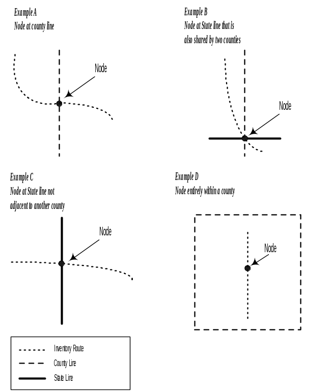
When nodes occur at boundaries between adjoining counties, Item 3a will identify one of the two counties sharing the boundary at the node and Item 3b will identify the other county (Figure V-11, Examples A and B). The counties can be identified in any sequence. If the node occurs at a boundary of three or more counties, any two of the possible three will be reported.
Figure
V-11. Nodes and Political Boundaries
Use the three-digit FIPS county code. (See Item 4 of the HPMS Universe Data Coding Instructions in Chapter IV.)
Adjoining counties of neighboring States, under any of the above-described conditions, are not to be coded.
Item 3b – County FIPS Code No. 2 (Length = 3)
This item identifies the second of the two counties sharing the boundary at the node, as discussed above.
Item 4 – Record Status (Length = 1)
This item depicts the condition of the node relative to the data submittal of the past year; that is, a newly created node or an existing node which has incurred a change in one or more of the data items represented in the Node File. In the first year's submittal, all nodes should be coded “0.” In subsequent years, if a node is added or one or more of the characteristics have changed, it will be coded as either “2” or “1,” respectively. If no change occurs to an existing node, then it will be coded “0.” When a node is reported as being deleted, it must be dropped from subsequent years' submittals. For example, where a realignment occurs along a route and the old alignment no longer qualifies as part of the “Base Network,” the old node(s) will be deleted and new node(s) will be added as needed.
Code |
Description |
0 |
No Change |
1 |
Changed - one or more data items on the node list have been changed or added |
2 |
New Node |
3 |
Deleted Node |
Item 5 – Node Number (Length = 10)
All nodes must be identified with a number that can be comprised of both alpha characters and numbers. Each node number must be unique within the State and right justified in the field.
Node Types: Items 6-11 represent different characteristics of a node. Nodes should be created based on one or more of these conditions. Mark each condition that applies to each node (all conditions that describe a particular node should be coded as “1”).
Item 6 – Inventory Route Intersection (Length = 1)
Node that occurs where two inventory routes intersect:
-
Code
Description
0
NO
1
YES
Item 7 – County Boundary (Length = 1)
Node that occurs where an inventory route is intersected by a county boundary:
-
Code
Description
0
NO
1
YES
Item 8 – State Boundary (Length = 1)
Node that occurs where an inventory route is intersected by a State boundary:
-
Code
Description
0
NO
1
YES
Note: Since a State line will also be a county boundary, Items 7 and 8 will both be coded as “1” at all State lines.
Item 9 – Equation (Length = 1)
Node that occurs where an equation occurs on an inventory route:
-
Code
Description
0
NO
1
YES
Item 10 – Spur Route Termini (Length = 1)
Node that occurs where an inventory route terminates without intersecting another inventory route:
-
Code
Description
0
NO
1
YES
Note: If this item is marked “yes,” Item 11 is also to be marked “yes.”
Item 11 – Inventory Route Termini (Length = 1)
Node that occurs where an inventory route begins, ends, stops at a discontinuity, or starts after a discontinuity.
-
Code
Description
0
NO
1
YES
Coordinates (Optional): Specify in the letter of transmittal whether these data exist, and the coordinate system and decimal positions (if any) used for the LRS submittal.
Item 12 – X Coordinate (Length = 10) (Optional)
Enter the “X” coordinate for the node. This should be a nonprojection geographic coordinate, preferably decimal degrees.
Item 13 – Y Coordinate (Length = 10) (Optional)
Enter the “Y” coordinate for the node. This should be a nonprojection geographic coordinate, preferably decimal degrees.
Other Descriptors (Optional)
Item 14 – Description of Node (Length = 100) (Optional)
This item is provided if the State desires to provide additional descriptive information regarding node location. Any alphanumeric characters may be entered, including blanks.
Inventory Route Link Data File Coding Instructions
The Inventory Route Link Data File, together with the Node Data File and maps, are used to define the geographic location of the inventory route and the KMPTs/MPTs. This record compliments the data supplied in the Node Data File and the Inventory Route and Node Map. A link is the roadway between two nodes. The Inventory Route and Node Map illustrates the locations of the links and nodes. All data in this file must be right justified and zero filled.
Item Number |
Position |
Length |
Data Type |
Data Item Description |
Identification |
||||
1 |
1-4 |
4 |
N |
Year |
2 |
5-6 |
2 |
N |
State FIPS Code |
3 |
7-9 |
3 |
N |
County FIPS Code |
4 |
10 |
1 |
N |
Record Status |
5 |
11-20 |
10 |
AN |
Inventory Route Number |
6 |
21-22 |
2 |
N |
Inventory Subroute Number |
7 |
23-32 |
10 |
AN |
Beginning Node Number |
8 |
33-40 |
8 |
N |
Beginning Milepoint/Kilometerpoint |
9 |
41-50 |
10 |
AN |
Ending Node Number |
10 |
51-58 |
8 |
N |
Ending Milepoint/Kilometerpoint |
Signed Route 1 |
||||
11 |
59 |
1 |
N |
Route Signing 1 |
12 |
60 |
1 |
N |
Route Qualifiers 1 |
13 |
61-68 |
8 |
AN |
Route Number 1 |
Signed Route 2 |
||||
14 |
69 |
1 |
N |
Route Signing 2 |
15 |
70 |
1 |
N |
Route Qualifiers 2 |
16 |
71-78 |
8 |
AN |
Route Number 2 |
Signed Route 3 |
||||
17 |
79 |
1 |
N |
Route Signing 3 |
18 |
80 |
1 |
N |
Route Qualifiers 3 |
19 |
81-88 |
8 |
AN |
Route Number 3 |
Other |
||||
20 |
89-118 |
30 |
AN |
Street Name |
N = Numeric AN = Alphanumeric |
||||
All data must be right justified and zero-filled. Beginning and ending node numbers must be right justified.
Data Item Details
Identification
Item 1 – Year (Length = 4)
See Item 1 of the HPMS Universe Data Coding Instructions in Chapter IV.
Item 2 – State FIPS Code (Length = 2)
See Item 2 of the HPMS Universe Data Coding Instructions in Chapter IV.
Item 3 – County FIPS Code (Length = 3)
See Item 4 of the HPMS Universe Data Coding Instructions in Chapter IV.
Item 4 – Record Status (Length = 1)
This item depicts the status of the route link, relative to the previous year's submittal; that is, a newly created link or an existing link which has incurred a change or addition to one or more of the data items represented in the link file. In the first year's submittal, all links must be coded “0.” In subsequent years, if a link is added or one or more of its characteristics have changed, it will be coded as either “2” or “1,” respectively. However, if no change occurs to an existing link, then it will be coded “0.” When a link is reported as being deleted, it must be dropped from subsequent years' submittals. For example, where a realignment occurs along a route and the old alignment no longer qualifies as part of the “Base Network,” the old link(s) will be deleted and new links(s) will be added as needed.
Code |
Description |
0 |
No Change |
1 |
Changed - one or more data items on the Route Link record has changed |
2 |
New Route Link |
3 |
Deleted Route Link |
Item 5 – Inventory Route Number (Length = 10)
The inventory route number, which is not necessarily the same as that posted along the roadway, is a number used to uniquely identify a route for inventory purposes. The inventory route number must be unique within a county, but it is recommended that it be unique within the State. This number can be alphanumeric, but must not contain blanks; it must be right justified in the field. Provide leading zeroes.
Item 6 – Inventory Subroute Number (Length = 2)
This number is used to uniquely identify portions of an inventory route within a county where certain conditions (KMPT/MPT equations, inventory route breaks, or KMPTs/MPTs that are adjusted at county boundaries) create a length of roadway with a duplicate KMPT/MPT or range of KMPTs/MPTs. A new subroute number must be assigned each time a duplicate KMPT/MPT or range of KMPTs/MPTs is encountered. These subroute numbers must only be unique within each county. In the absence of duplicate KMPTs/MPTs and previous to the first duplicate KMPT/MPT condition encountered, code zero.
Item 7 – Beginning Node Number (Length = 10)
This is the number of the first of two nodes of the link. This node is at the end of the link with the lowest KMPT/MPT.
Item 8 – Beginning Milepoint/Kilometerpoint (xxxx.xxx — code the decimal)(Length = 8)
This is the lowest KMPT/MPT of the link.
Item 9 – Ending Node Number (Length = 10)
This is the number of the last of two nodes of the link. This node is at the end of the link with the highest KMPT/MPT of the link.
Item 10 – Ending Milepoint/Kilometerpoint (xxxx.xxx — code the decimal)(Length = 8)
This is the highest KMPT/MPT of the link.
Signed Routes 1, 2, and 3: These three groups of three items define up to three signed route numbers assigned to a link. The priority of the signed routes shall be based on Item 11 below, where those with a non-zero lower code have the higher priority.
Items 11, 14, and 17 – Route Signing 1, 2, and 3 (Length = 1)
These codes specify the manner in which the highway segment is signed.
Code |
Description |
0 |
Not Signed or No More Signed Routes |
1 |
Interstate |
2 |
U.S. |
3 |
State |
4 |
Off-Interstate Business Markers |
5 |
County |
6 |
Township |
7 |
Municipal |
8 |
Parkway |
9 |
None of the Above |
Items 12, 15, and 18 – Route Qualifiers 1, 2 and 3 (Length = 1)
These codes specify the manner in which the highway segment is signed. Where more than one code is applicable, use the lower code excluding zero.
-
Code
Description
0
No Qualifier
1
Alternate
2
Business Route
3
Bypass
4
Spur
5
Loop
6
Proposed
7
Temporary
8
Truck Route
9
None of the Above
Items 13, 16, and 19 – Route Number 1, 2 and 3 (Length = 8)
Enter the signed route number (on the marker), right justified. Any alphabetic character prefixes or suffixes that cannot be identified with the Route Signing or Qualifier list of codes should be reported and abbreviated to fit into the field length, if necessary. Zero-fill if the route is unsigned or there are no more signed routes.
Item 20 – Street Name (Length = 30)
Enter a street, road, or highway name. This field need only be used when a signed route number is not available for use in describing the route. Otherwise, leave the field blank. If used, ensure that the name includes the proper suffix (street, place, court, etc.) to eliminate duplicate name possibilities.
For example: U.S. 5 Business Route and State 2 Truck Route are on the same link:
Item 11 = “2” (U.S.)
Item 12 = “2” (Business Route)
Item 13 = “00000005” (Route Number)
Item 14 = “3” (State)
Item 15 = “8” (Truck Route)
Item 16 = “00000002” (Route Number)
LRS Submittal Option 2 - LRSEDIT Files Plus Maps for New Links and Nodes
An LRSEDIT file for the complete base highway network with a copy of the LRSEDIT printed reports must be submitted along with maps depicting new links and nodes that did not exist on the NHPN. Maps must be labeled in accordance with instructions for coding inventory route and node maps under Option 1 above. Beginning and ending kilometerpoints/milepoints for the links must also be included.
LRS Submittal Option 3 - GIS Files
A complete GIS file encompassing the base highway network shall be submitted. This file shall contain all data required by Chapter V in a format agreed upon by the State and FHWA.
LRS Updates
After the initial reporting of LRS data, only updated information is required on an annual basis. LRS reporting status should be noted in the comment file, annually.
Technical Assistance
For technical assistance or further information regarding this chapter or about LRS, please contact
Roger Petzold of the Federal Highway Administration; Phone: 202-366-4074, E-mail: [email protected].
V-
| File Type | application/msword |
| File Modified | 0000-00-00 |
| File Created | 0000-00-00 |
© 2026 OMB.report | Privacy Policy
